Difference between revisions of "NKB1000 RS485 Setup"
(→How to wire the NKB1000's RS485 port:) |
(→How to Configure the NKB1000 for RS485) |
||
| (13 intermediate revisions by one other user not shown) | |||
| Line 6: | Line 6: | ||
===How to wire the NKB1000's RS485 port:=== | ===How to wire the NKB1000's RS485 port:=== | ||
| − | 1. From the PTZ's | + | 1. From the PTZ's RS485 harness (or NVR) wire the positive to the positive and the negative to the negative. This picture will show a connector used as a junction for the PTZ to the CAT 5.E cable. (PTZ- Orange to CAT 5.E Blue, and PTZ Yellow to CAT 5.E White and green stripe) |
| − | + | *From PTZ RS485 Harness | |
| − | [[file: | + | [[file:nkb100012345.JPG|500x500px]] |
OR | OR | ||
| + | *From NVR/DVR/HCVR RS485 connector | ||
| + | [[file:NKB1000RS485ToNVR.JPG|500x500px]] | ||
| − | |||
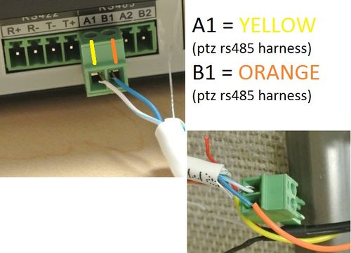
| + | 2. On the NKB1000's back side connect and wire in a 2 prong junction connector, With A1 (CAT 5.E White and green stripe aka Yellow on PTZ's RS485 harness) and B1 (CAT 5.E Blue aka Orange on PTZ's RS485 harness) | ||
| − | |||
| + | [[file:NKB1000RS485ToPTZ1.JPG|500x500px]] | ||
| − | + | ===RS485 Types of connections=== | |
| − | |||
| − | + | *There are several ways to wire the RS485 connection on the NKB1000: | |
| − | *There are several ways to wire the | ||
1.RS485-RS232 Switch Boxes | 1.RS485-RS232 Switch Boxes | ||
| Line 37: | Line 37: | ||
2.Multi-keyboard link via RS485: | 2.Multi-keyboard link via RS485: | ||
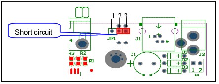
| − | You can use the following figure if you are connecting multiple keyboards via RS485 port. The last converter on | + | You can use the following figure if you are connecting multiple keyboards via RS485 port. The last converter on RS485 port must be short circuited. (E.g.: open converter). See the image below, you need to change [1-2] short circuit to [2-3] short circuit. |
| Line 48: | Line 48: | ||
[[file:NKB1000RS485PTZtoCAT5ETNKB.jpg|500x500px]] | [[file:NKB1000RS485PTZtoCAT5ETNKB.jpg|500x500px]] | ||
| − | ---- | + | ===How to Configure the NKB1000 for RS485=== |
| + | |||
| + | *Direct Connection | ||
| + | |||
| + | 1. Please make sure keyboard A/B line and speed dome A/B line connection is right. | ||
| + | |||
| + | |||
| + | |||
| + | 2. Set speed dome address so that the speed dome address and the keyboard RS485 address are the same | ||
| + | |||
| + | |||
| + | |||
| + | [[File:NKB1000RS4859.JPG|500x500px]] | ||
| + | |||
| + | |||
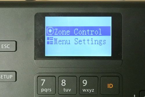
| + | 3.Go to the zones interface of the keyboard | ||
| + | |||
| + | |||
| + | [[File:NKB1000RS4858.JPG|500x500px]] | ||
| + | |||
| + | |||
| + | *Please select protocol according to the speed dome type. The default setup is DH-SD | ||
| + | *Please login WEB of the speed dome, from main interface->Setup->System->PTZ to | ||
| + | view speed dome address, protocol, COM setup and etc | ||
| + | |||
| + | |||
| + | [[file:NKB1000RS4856.JPG|500x500px]] | ||
| + | |||
| + | |||
| + | 4. After the setup, click 【ESC】 to exit control point control interface. System pops up a dialogue box you can click 【ENTER】 to save data or click 【ESC】 to cancel setup | ||
| + | |||
| + | |||
| + | *Operation | ||
| + | |||
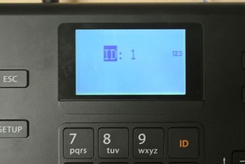
| + | 1. On the keyboard, click 【ID】 to go to the control point interface to set speed dome ID to connect to the speed dome | ||
| + | |||
| + | |||
| + | [[File:NKB1000RS4858.JPG|500x500px]] | ||
| + | |||
| + | |||
| + | 2. After successful connection, the interface is shown as below | ||
| + | |||
| + | |||
| + | [[File:NKB1000RS4851.JPG|500x500px]] | ||
| + | |||
| + | |||
| + | * Step: The move speed. Input number buttons on the keyboard and then click 【ENTER】 to confirm. The speed ranges from 1 to 8. The step 1 is faster than step 8 | ||
| + | * The lens movement supports 8 directions. It includes: up/down/left/right/top left/top right/bottom left/bottom right. Please use the joystick to control | ||
| + | |||
| + | |||
| + | |||
| + | |||
[[Category:Network Keyboard]] | [[Category:Network Keyboard]] | ||
| Line 54: | Line 105: | ||
[[Category:Remote Access]] | [[Category:Remote Access]] | ||
[[Category:PTZ]] | [[Category:PTZ]] | ||
| + | |||
| + | |||
| + | {{Template:Footer:Remote_Access}} | ||
Latest revision as of 19:11, 4 November 2020
Contents
How to Setup NKB1000 via RS485
For DH-NKB1000, DH-KBD1000, or DH-KB1000
- NOTE: RS485 transmission distance is 1200 m(9600bps)
How to wire the NKB1000's RS485 port:
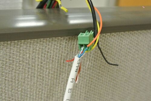
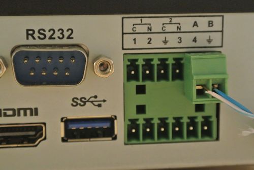
1. From the PTZ's RS485 harness (or NVR) wire the positive to the positive and the negative to the negative. This picture will show a connector used as a junction for the PTZ to the CAT 5.E cable. (PTZ- Orange to CAT 5.E Blue, and PTZ Yellow to CAT 5.E White and green stripe)
- From PTZ RS485 Harness
OR
- From NVR/DVR/HCVR RS485 connector
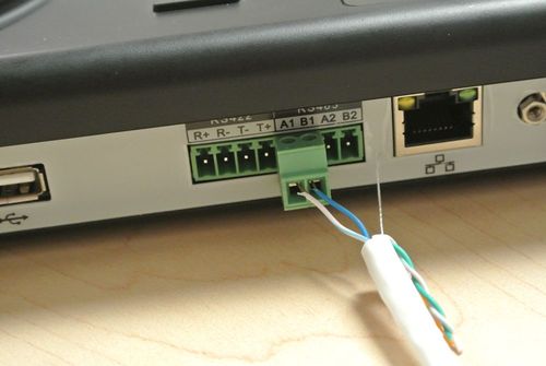
2. On the NKB1000's back side connect and wire in a 2 prong junction connector, With A1 (CAT 5.E White and green stripe aka Yellow on PTZ's RS485 harness) and B1 (CAT 5.E Blue aka Orange on PTZ's RS485 harness)
RS485 Types of connections
- There are several ways to wire the RS485 connection on the NKB1000:
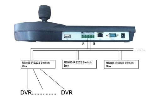
1.RS485-RS232 Switch Boxes You can user one RS485 to RS232 switch box (provided) connect with DVR RS232 port One RS485 bus can connect with thirty-two RS485-RS232 switch boxes,one RS485-RS232 switch box can connect with twelve DVRs
2.Multi-keyboard link via RS485:
You can use the following figure if you are connecting multiple keyboards via RS485 port. The last converter on RS485 port must be short circuited. (E.g.: open converter). See the image below, you need to change [1-2] short circuit to [2-3] short circuit.
3. Directly linked to the PTZ:
How to Configure the NKB1000 for RS485
- Direct Connection
1. Please make sure keyboard A/B line and speed dome A/B line connection is right.
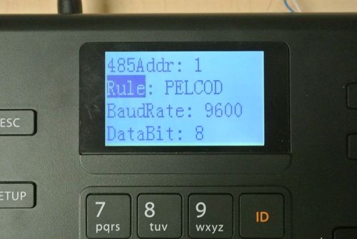
2. Set speed dome address so that the speed dome address and the keyboard RS485 address are the same
3.Go to the zones interface of the keyboard
- Please select protocol according to the speed dome type. The default setup is DH-SD
- Please login WEB of the speed dome, from main interface->Setup->System->PTZ to
view speed dome address, protocol, COM setup and etc
4. After the setup, click 【ESC】 to exit control point control interface. System pops up a dialogue box you can click 【ENTER】 to save data or click 【ESC】 to cancel setup
- Operation
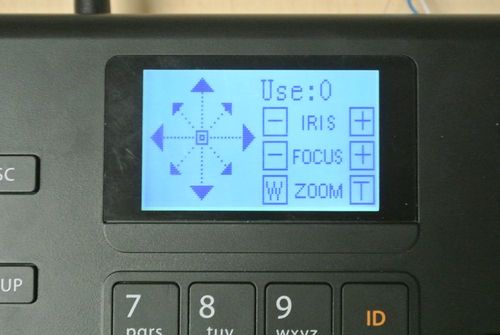
1. On the keyboard, click 【ID】 to go to the control point interface to set speed dome ID to connect to the speed dome
2. After successful connection, the interface is shown as below
- Step: The move speed. Input number buttons on the keyboard and then click 【ENTER】 to confirm. The speed ranges from 1 to 8. The step 1 is faster than step 8
- The lens movement supports 8 directions. It includes: up/down/left/right/top left/top right/bottom left/bottom right. Please use the joystick to control
