Notice: Firmware Links Under Maintenance We are currently undergoing maintenance on all firmware links. If any links are inaccessible, please email or contact Tech Support for the firmware. We appreciate your patience during the maintenance, thank you for your understanding.
Difference between revisions of "NVR/Recording Setup/Physical Alarm"
(→Physical Alarm Setup) |
(→Physical Alarm Setup) |
||
| Line 12: | Line 12: | ||
'''STEP 2.''' Connect the N.C. (Normally Closed) wire to one of the numbered ports. Connect the COM wire to the COM / Ground Port. | '''STEP 2.''' Connect the N.C. (Normally Closed) wire to one of the numbered ports. Connect the COM wire to the COM / Ground Port. | ||
| − | Ala r m Inputs are grouped in fours. Each group uses the Communication/Ground Port on the right. | + | Ala r m Inputs are grouped in fours. |
| + | *Each group uses the Communication/Ground Port on the right. | ||
[[File:physical_alarm_2.png|none|889x500px]] | [[File:physical_alarm_2.png|none|889x500px]] | ||
Revision as of 20:57, 30 December 2015
Physical Alarm Setup
Please Note: Setting up alarm triggers will only work with recorders that have alarm inputs.
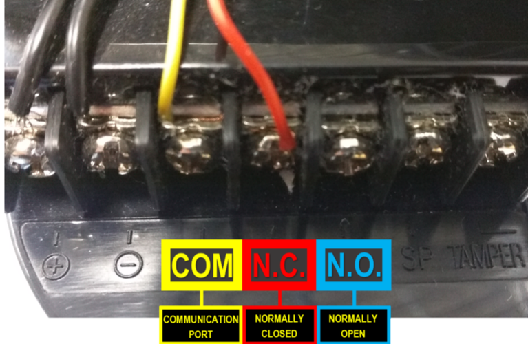
STEP 1. Identify the connections on the Alarm Trigger.
- COM: Communication Port or Ground N.C: Normally Closed - A Trigger that initiates when an object disrupts the communication line of 2 sensors
- N.C: Normally Closed - A Trigger that initiates when an object disrupts the communication line of 2 sensors
- N.O: Normally Open - A Trigger that initiates when an object completes the communication line of 2 sensors.
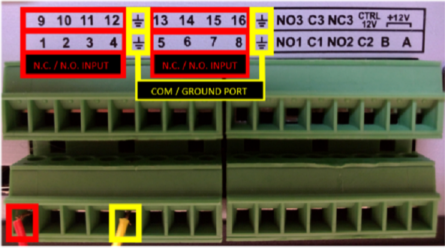
STEP 2. Connect the N.C. (Normally Closed) wire to one of the numbered ports. Connect the COM wire to the COM / Ground Port.
Ala r m Inputs are grouped in fours.
- Each group uses the Communication/Ground Port on the right.

