Thermal/Temperature Monitoring/Camera Configuration
Temperature Monitoring Solution Camera Configuration
This guide will cover the camera Configuration for the Thermal Temperature Monitoring Solution
Prerequisites
- DH-TPC-BF3221-T or DH-TPC-BF5421-T Thermal Hybrid Network Camera
- JQ-D70Z Blackbody
- Temperature Monitoring Physical Setup guide followed
- Thermal camera updated to latest firmware - How To Update TPC-BF5421-T Firmware
Video Instructions
Step by Step Instructions
The camera should be upgraded to the correct firmware and initialized before setup. Please follow How To Update TPC-BF5421-T Firmware before attempting this guide
1.
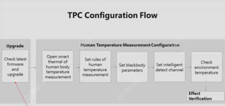
![]() Check latest firmware and upgrade
Check latest firmware and upgrade
How To Setup Alarm Record
Prerequisites
- Dahua device that supports Alarm Input recording
- Physical alarm devices wired into Dahua devices - How To Connect A Physical Alarm To A Dahua Device
Video Tutorial
Step by Step Instructions
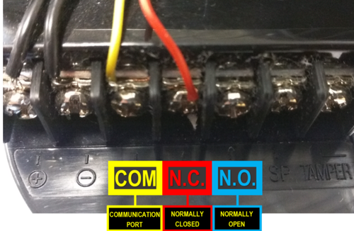
STEP 1. Identify the connections on the Alarm Trigger.
- COM: Communication Port or Ground N.C: Normally Closed - A Trigger that initiates when an object disrupts the communication line of 2 sensors
- N.C: Normally Closed - A Trigger that initiates when an object disrupts the communication line of 2 sensors
- N.O: Normally Open - A Trigger that initiates when an object completes the communication line of 2 sensors.
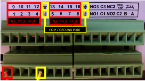
STEP 2. Connect the N.C. (Normally Closed) wire to one of the numbered ports. Connect the COM wire to the COM / Ground Port.
- Alarm Inputs are grouped in fours.
- Each group uses the Communication/Ground Port on the right. Alarm Inputs are grouped in fours. Each group uses the Communication/Ground Port on the right.
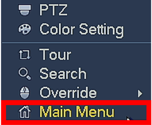
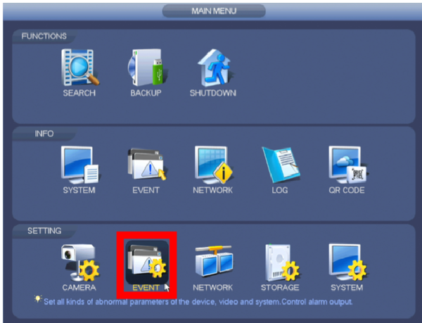
STEP 3. From your local GUI, right click on your live view screen and click on Main Menu.
STEP 4.Click Event from the Settings menu option.
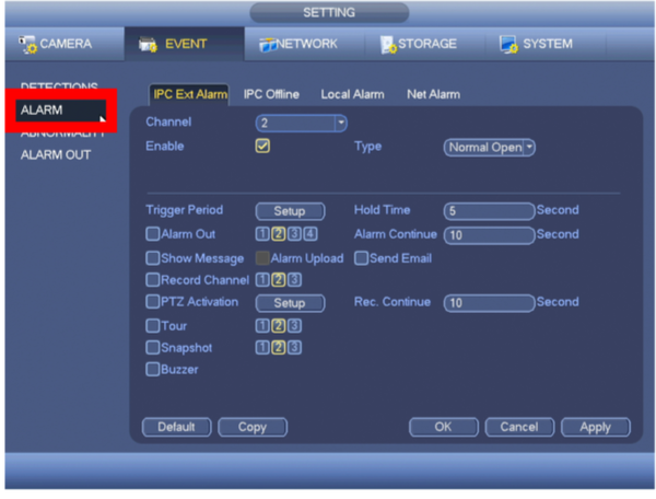
STEP 5. From the left menu tab, click Alarm.
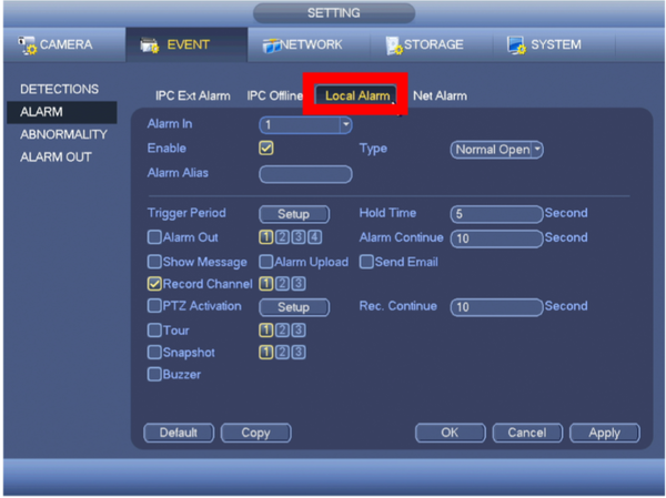
STEP 6. Click on Local Alarm tab.
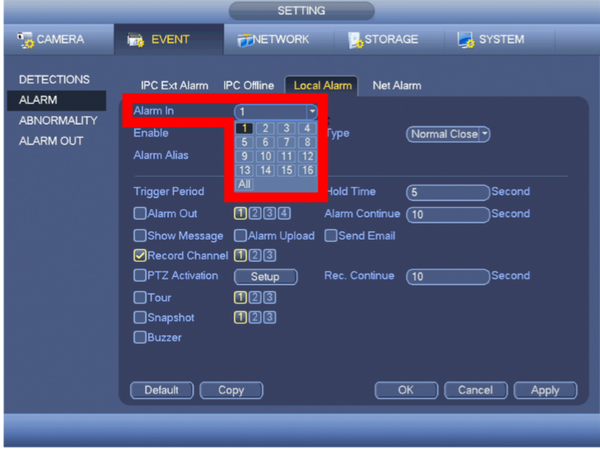
STEP 7. Select the Alarm In Port you connected from Step 2.
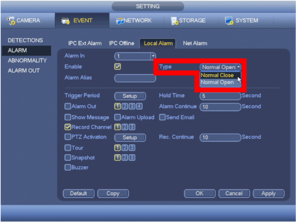
STEP 8. Select alarm trigger Type
- Normally Closed: A Trigger that initiates when an object disrupts the communication line of 2 sensors.
- Normally Open: A Trigger that initiates when an object completes the communication line of 2 sensors.
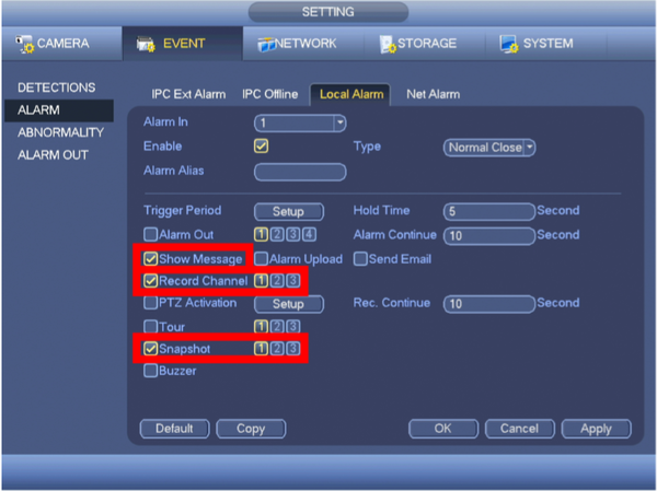
STEP 9. Configure the Alarm Trigger Settings
- Show Message: An alert will appear on the display attached to the system when the alarm is triggered.
- Record Channel: Configure the alarm to trigger recording on a specific channel, or all.
- Snapshot: A Snapshot will be taken by a specific channel or all when the alarm is triggered.
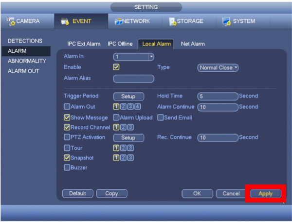
STEP 10. Click Apply.
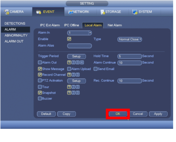
STEP 11. Click OK
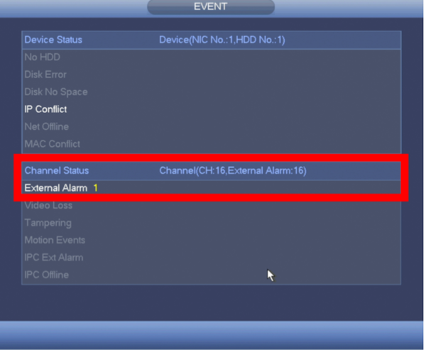
- If you configured the Alarm to "Show a Message", it will appear as soon as the alarm is triggered.
- Right-Click your mouse once to clear the message.
![]() Open smart thermal of human body temperature measurement
Open smart thermal of human body temperature measurement
How To Setup Alarm Record
Prerequisites
- Dahua device that supports Alarm Input recording
- Physical alarm devices wired into Dahua devices - How To Connect A Physical Alarm To A Dahua Device
Video Tutorial
Step by Step Instructions
STEP 1. Identify the connections on the Alarm Trigger.
- COM: Communication Port or Ground N.C: Normally Closed - A Trigger that initiates when an object disrupts the communication line of 2 sensors
- N.C: Normally Closed - A Trigger that initiates when an object disrupts the communication line of 2 sensors
- N.O: Normally Open - A Trigger that initiates when an object completes the communication line of 2 sensors.
STEP 2. Connect the N.C. (Normally Closed) wire to one of the numbered ports. Connect the COM wire to the COM / Ground Port.
- Alarm Inputs are grouped in fours.
- Each group uses the Communication/Ground Port on the right. Alarm Inputs are grouped in fours. Each group uses the Communication/Ground Port on the right.
STEP 3. From your local GUI, right click on your live view screen and click on Main Menu.
STEP 4.Click Event from the Settings menu option.
STEP 5. From the left menu tab, click Alarm.
STEP 6. Click on Local Alarm tab.
STEP 7. Select the Alarm In Port you connected from Step 2.
STEP 8. Select alarm trigger Type
- Normally Closed: A Trigger that initiates when an object disrupts the communication line of 2 sensors.
- Normally Open: A Trigger that initiates when an object completes the communication line of 2 sensors.
STEP 9. Configure the Alarm Trigger Settings
- Show Message: An alert will appear on the display attached to the system when the alarm is triggered.
- Record Channel: Configure the alarm to trigger recording on a specific channel, or all.
- Snapshot: A Snapshot will be taken by a specific channel or all when the alarm is triggered.
STEP 10. Click Apply.
STEP 11. Click OK
- If you configured the Alarm to "Show a Message", it will appear as soon as the alarm is triggered.
- Right-Click your mouse once to clear the message.

