Difference between revisions of "NVRiSettingNetwork"
(Created page with "==NVR Interface-Setting-Network== ===TCP/IP=== ===Connection=== ===WIFI=== ===3G=== ===PPPoE=== ===DDNS=== ===UPnP=== ===IP Filter=== ===EMail=== ===FTP=== ===Multicast=== ===...") |
|||
| (38 intermediate revisions by 2 users not shown) | |||
| Line 1: | Line 1: | ||
==NVR Interface-Setting-Network== | ==NVR Interface-Setting-Network== | ||
| + | <imagemap> | ||
| + | Image:NVRiSettingNetwork.png | ||
| + | rect 0 25 122 60 [[NVRiSettingCamera]] | ||
| + | rect 122 26 246 60 [[NVRiSettingNetwork]] | ||
| + | rect 248 27 369 61 [[NVRiSettingEvent]] | ||
| + | rect 370 27 492 61 [[NVRiSettingStorage]] | ||
| + | rect 493 27 616 61 [[NVRiSettingSystem]] | ||
| + | desc none | ||
| + | </imagemap> | ||
| + | |||
===TCP/IP=== | ===TCP/IP=== | ||
| + | [[file:NVRiSettingNetworkTCPIP.png]] | ||
| + | |||
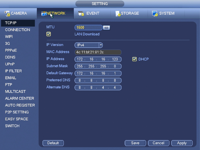
| + | The single network adapter interface is shown as in Figure 4‑99 and the dual network adapters interface is shown as in Figure 4‑100. | ||
| + | |||
| + | * Network Mode : Includes multiple access, fault tolerance, and load balancing | ||
| + | ** Multiple-address mode: eth0 and eth1 operate separately. You can use the services such as HTTP, RTP service via etho0 or the eth1. Usually you need to set one default card (default setup is etho) to request the auto network service form the device-end such as DHCP, email, FTP and etc. In multiple-address mode, system network status is shown as offline once one card is offline. | ||
| + | ** Network fault-tolerance: In this mode, device uses bond0 to communicate with the external devices. You can focus on one host IP address. At the same time, you need to set one master card. Usually there is only one running card (master card).System can enable alternate card when the master card is malfunction. The system is shown as offline once these two cards are both offline. Please note these two cards shall be in the same LAN. | ||
| + | ** Load balance: In this mode, device uses bond0 to communicate with the external device. The eth0 and eth1 are both working now and bearing the network load. Their network load are general the same. The system is shown as offline once these two cards are both offline. Please note these two cards shall be in the same LAN. | ||
| + | * Default Network Card: Please select eth0/eth1/bond0(optional) after enable multiple-access function | ||
| + | * Main Network Card: Please select eth0/eth1 (optional).after enable multiple access function. | ||
| + | |||
| + | '''Note: The dual-Ethernet port series support the above three configurations and supports functions as multiple-access, fault-tolerance and load balancing.''' | ||
| + | |||
| + | * IP Version: There are two options: IPv4 and IPv6. Right now, system supports these two IP address format and you can access via them. | ||
| + | * MAC address: The host in the LAN can get a unique MAC address. It is for you to access in the LAN. It is read-only. | ||
| + | * IP address: Here you can use up/down button (pq) or input the corresponding number to input IP address. Then you can set the corresponding subnet mask the default gateway. | ||
| + | * Default gateway: Here you can input the default gateway. Please note system needs to check the validity of all IPv6 addresses. The IP address and the default gateway shall be in the same IP section. That is to say, the specified length of the subnet prefix shall have the same string. | ||
| + | * DHCP: It is to auto search IP. When enable DHCP function, you can not modify IP/Subnet mask /Gateway. These values are from DHCP function. If you have not enabled DHCP function, IP/Subnet mask/Gateway display as zero. You need to disable DHCP function to view current IP information. Besides, when PPPoE is operating, you can not modify IP/Subnet mask /Gateway. | ||
| + | * MTU: It is to set MTU value of the network adapter. The value ranges from 1280-7200 bytes. The default setup is 1500 bytes. Please note MTU modification may result in network adapter reboot and network becomes off. That is to say, MTU modification can affect current network service. System may pop up dialog box for you to confirm setup when you want to change MTU setup. Click OK button to confirm current reboot, or you can click Cancel button to terminate current modification. Before the modification, you can check the MTU of the gateway; the MTU of the NVR shall be the same as or is lower than the MTU of the gateway. In this way, you can reduce packets and enhance network transmission efficiency. | ||
| + | |||
| + | The following MTU value is for reference only. | ||
| + | |||
| + | * 1500: Ethernet information packet max value and it is also the default value. It is the typical setup when there is no PPPoE or VPN. It is the default setup of some router, switch or the network adapter. | ||
| + | * 1492: Recommend value for PPPoE. | ||
| + | * 1468: Recommend value for DHCP. | ||
| + | |||
| + | * Preferred DNS server: DNS server IP address. | ||
| + | * Alternate DNS server: DNS server alternate address. | ||
| + | * Transfer mode: Here you can select the priority between fluency/video qualities. | ||
| + | * LAN download: System can process the downloaded data first if you enable this function. The download speed is 1.5X or 2.0X of the normal speed. | ||
| + | * LAN download: System can process the downloaded data first if you enable this function. The download speed is 1.5X or 2.0X of the normal speed. | ||
| + | |||
| + | After completing all the setups please click save button, system goes back to the previous menu. | ||
| + | |||
===Connection=== | ===Connection=== | ||
| + | [[file:NVRiSettingNetworkConnection.png]] | ||
| + | |||
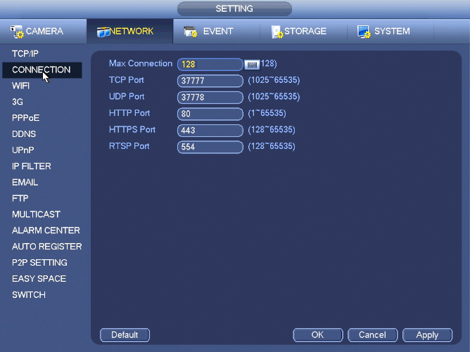
| + | The connection setup interface is shown below: | ||
| + | |||
| + | * Max connection: system support maximal 128 users. 0 means there is no connection limit. | ||
| + | * TCP port: Default value is 37777. | ||
| + | * UDP port: Default value is 37778. | ||
| + | * HTTP port: Default value is 80. | ||
| + | * HTTPS port: Default value is 443. | ||
| + | * RTSP port: Default value is 554. | ||
| + | |||
| + | Important: System needs to reboot after you changed and saved any setup of the above four ports. Please make sure the port values here do not conflict. | ||
| + | |||
===WIFI=== | ===WIFI=== | ||
| + | [[file:NVRiSettingNetworkWIFI.png]] | ||
| + | |||
| + | '''Note: '''This function is for some series product only. | ||
| + | |||
| + | |||
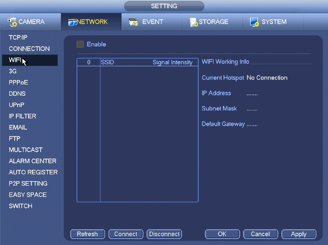
| + | The WIFI interface is shown as below. | ||
| + | |||
| + | * Enable: Check the box here to enable WIFI function. | ||
| + | * Refresh: You can click it to search the hotspot list again. It can automatically add the information such as the password if you have set it before. | ||
| + | * Disconnect: Here you can click it to turn off the connection. | ||
| + | * Connect: Here you can click it to connect to the hotspot. System needs to turn off current connection and then connect to a new hotspot if there is connection of you selected one. | ||
| + | * WIFI working status: Here you can view current connection status. | ||
| + | |||
| + | Please note: | ||
| + | |||
| + | * After successful connection, you can see WIFI connection icon at the top right corner of the preview interface. | ||
| + | * When the hotspot verification type is WEP, system displays as AUTO since the device can not detect its encryption type. | ||
| + | * System does not support verification type WPA and WPA2. The display may become abnormal for the verification type and encryption type. | ||
| + | |||
| + | After device successfully connected to the WIFI, you can view the hotspot name, IP address, subnet mask, default gateway and etc. Right now system support TOTOLINK_N2200UP module. | ||
| + | |||
===3G=== | ===3G=== | ||
| + | [[file:NVRiSettingNetwork3G.png]] | ||
| + | |||
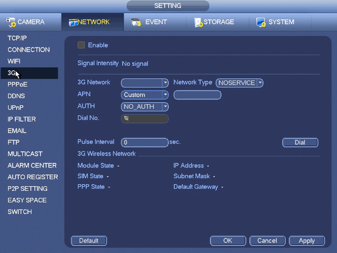
| + | 3G setup interface is shown as below. | ||
| + | |||
| + | Please refer to the following contents for the parameter information. | ||
| + | |||
| + | * Pane 1: Display 3G signal intensity after you enabled 3G | ||
| + | * Pane 2: Display 3G module configuration information after you enabled 3G | ||
| + | * Pane 3: Display 3G module status information after you enabled 3G | ||
| + | |||
| + | It is to display current wireless network signal intensity such as EVDO, CDMA1x, WCDMA, WCDMA, EDGE and etc. | ||
| + | |||
| + | * 3G module: It is to display current wireless network adapter name. | ||
| + | * 3G Enable/Disable: Check the box here to enable 3G | ||
| + | * Network type: There are various network types for different 3G network modules. You can select according to your requirements. | ||
| + | * APN: It is the wireless connection server. It is to set you access the wireless network via which method. | ||
| + | * AUTH: It is the authentication mode. It supports PAP/CHAP. | ||
| + | * Dial number: Please input 3G network dialup number you got from your ISP. | ||
| + | * User name: It is the user name for you to login the 3G | ||
| + | * Password: It is the password for you to login the 3G | ||
| + | * Pulse interval: You can set dialup duration. Once you disable the extra stream, the connection time begins. For example, if you input 5 seconds here, then 3G network connection period is 5 seconds. The device automatically disconnect when time is up. If there is no extra stream, 3G network connection is valid all the time.''' If the alive time is 0, then the 3G network connection is valid all the time.''' | ||
| + | * Dial: Here you can enable or disable 3G network connection/disconnection manually. | ||
| + | * 3G wireless network: Here is to display wireless network status, SIM card status, dial status. If the 3G connection is OK, then you can see the device IP address the wireless network automatically allocates. | ||
| + | |||
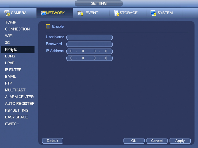
===PPPoE=== | ===PPPoE=== | ||
| + | [[file:NVRiSettingNetworkPPPoE.png]] | ||
| + | |||
| + | PPPoE interface is shown in the above image. | ||
| + | Input “PPPoE name” and “PPPoE password” you get from your ISP (Internet service provider). | ||
| + | Click save button, you need to restart to activate your configuration. | ||
| + | After rebooting, NVR will connect to internet automatically. The IP in the PPPoE is the NVR dynamic value. You can access this IP to visit the unit. | ||
| + | |||
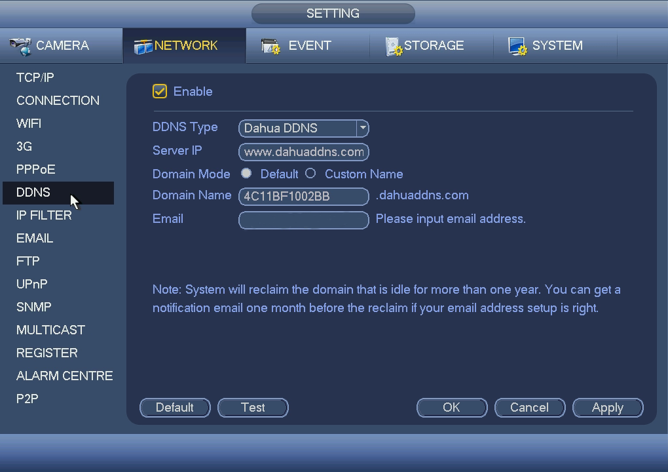
===DDNS=== | ===DDNS=== | ||
| + | DDNS setup interface is shown below. | ||
| + | |||
| + | You need a PC of fixed IP in the internet and there is the DDNS software running in this PC. In other words, this PC is a DNS (domain name server). | ||
| + | |||
| + | In network DDNS, please select DDNS type and highlight enable item. Then input your PPPoE name you get from you IPS and server IP (PC with DDNS). Click save button and then reboot system. | ||
| + | |||
| + | Click save button, system prompts for rebooting to get all setup activated. | ||
| + | |||
| + | After rebooting, open IE and input as below: http://(DDNS server IP)/(virtual directory name)/webtest.htm e.g.: http://10.6.2.85/NVR _DDNS/webtest.htm.) | ||
| + | |||
| + | Now you can open DDNSServer web search page. | ||
| + | |||
| + | [[file:NVRiSettingNetworkDDNS.png|668px]] | ||
| + | |||
| + | Please note DDNS type includes: CN99 DDNS, NO-IP DDNS, Quick DDNS, Dyndns DDNS and sysdns DDNS. All the DDNS can be valid at the same time, you can select as you requirement. | ||
| + | |||
| + | Private DDNS function shall work with special DDNS server and special Professional Surveillance Software (PSS). | ||
| + | |||
| + | '''Quick DDNS and Client-end Introduction ''' | ||
| + | |||
| + | '''1) Background Introduction ''' | ||
| + | |||
| + | Device IP is not fixed if you use ADSL to login the network. The DDNS function allows you to access the NVR via the registered domain name. Besides the general DDNS ,the Quick DDNS works with the device from the manufacturer so that it can add the extension function. | ||
| + | |||
| + | '''2) Function Introduction ''' | ||
| + | |||
| + | The quick DDNS client has the same function as other DDNS client end. It realizes the bonding of the domain name and the IP address. Right now, current DDNS server is for our own devices only. You need to refresh the bonding relationship of the domain and the IP regularly. There is no user name, password or the ID registration on the server. At the same time, each device has a default domain name (Generated by MAC address) for your option. You can also use customized valid domain name (has not registered.). | ||
| + | |||
| + | '''3) Operation ''' | ||
| + | |||
| + | Before you use Quick DDNS, you need to enable this service and set proper server address, port value and domain name. | ||
| + | |||
| + | * Server address:quickddns.com | ||
| + | * Port number:80 | ||
| + | * Domain name:There are two modes: Default domain name and customized domain name. | ||
| + | |||
| + | Except default domain name registration, you can also use customized domain name (You can input your self-defined domain name.) After successful registration, you can use domain name to login installed of the device IP. | ||
| + | |||
| + | * User name: It is optional. You can input your commonly used email address. | ||
| + | |||
| + | '''Important ''' | ||
| + | |||
| + | * Do not register frequently. The interval between two registrations shall be more than 60 seconds. Too many registration requests may result in server attack. | ||
| + | * System may take back the domain name that is idle for one year. You can get a notification email before the cancel operation if your email address setup is OK. | ||
| + | |||
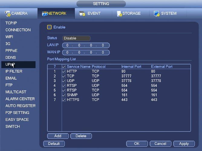
===UPnP=== | ===UPnP=== | ||
| + | [[file:NVRiSettingNetworkUPnP.png]] | ||
| + | |||
| + | The UPNP protocol is to establish a mapping relationship between the LAN and the WAN. Please input the router IP address in the LAN. | ||
| + | |||
| + | * UPNP on/off :Turn on or off the UPNP function of the device. | ||
| + | * Status: When the UPNP is offline, it shows as “Unknown”. When the UPNP works it shows “Success” | ||
| + | * Router LAN IP: It is the router IP in the LAN. | ||
| + | * WAN IP: It is the router IP in the WAN. | ||
| + | * Port Mapping list: The port mapping list here is the one to one relationship with the router’s port mapping setting. | ||
| + | * List: | ||
| + | ** Service name:Defined by user. | ||
| + | ** Protocol: Protocol type | ||
| + | ** Internal port:Port that has been mapped in the router. | ||
| + | ** External port:Port that has been mapped locally. | ||
| + | * Default: UPNP default port setting is the HTTP, TCP and UDP of the NVR. | ||
| + | * Add to the list: Click it to add the mapping relationship. | ||
| + | * Delete: Click it to remove one mapping item. | ||
| + | |||
| + | Double click one item; you can change the corresponding mapping information. | ||
| + | |||
| + | |||
| + | '''Important:''' | ||
| + | |||
| + | '''When you are setting the router external port, please use 1024~5000 port. Do not use well-known port 1~255 and the system port 256~1023 to avoid conflict.''' | ||
| + | |||
| + | '''For the TCP and UDP, please make sure the internal port and external port are the same to guarantee the proper data transmission. ''' | ||
| + | |||
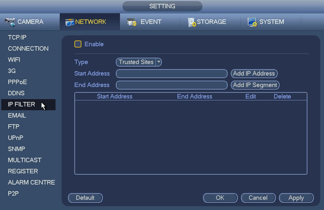
===IP Filter=== | ===IP Filter=== | ||
| + | [[file:NVRiSettingNetworkIPFilter.png|668px]] | ||
| + | |||
| + | You can add IP in the following list. The list supports max 64 IP addresses. System supports valid address of IPv4 and IPv6. | ||
| + | |||
| + | '''Please note system needs to check the validity of all IPv6 addresses and implement optimization.''' | ||
| + | |||
| + | After you enabled trusted sites function, only the IP listed below can access current NVR. | ||
| + | |||
| + | If you enable blocked sites function, the following listed IP addresses can not access current NVR. | ||
| + | |||
| + | * Enable: Highlight the box here, you can check the trusted site function and blocked sites function. You can not see these two modes if the Enable button is grey. | ||
| + | * Type: You can select trusted site from the dropdown list. You can view the IP address on the following column. | ||
| + | * Start address/end address: Select one type from the dropdown list, you can input IP address in the start address and end address. Now you can click Add IP address or Add IP section to add. | ||
| + | |||
| + | # For the newly added IP address, it is in enable status by default. Remove the √ before the item, and then current item is not in the list. | ||
| + | # System max supports 64 items. | ||
| + | # Address column supports IPv4 or IPv6 format. If it is IPv6 address, system can optimize it. For example, system can optimize aa:0000: 00: 00aa: 00aa: 00aa: 00aa: 00aa as aa:: aa: aa: aa: aa: aa: aa. | ||
| + | # System automatically removes space if there is any space before or after the newly added IP address. | ||
| + | # System only checks start address if you add IP address. System check start address and end address if you add IP section and the end address shall be larger than the start address. | ||
| + | # System may check newly added IP address exists or not. System does not add if input IP address does not exist. | ||
| + | |||
| + | * Delete: Click it to remove specified item. | ||
| + | * Edit: Click it to edit start address and end address. See Figure 4‑110. System can check the IP address validity after the edit operation and implement IPv6 optimization. | ||
| + | * Default: Click it to restore default setup. In this case, the trusted sites and blocked sites are both null. | ||
| + | |||
| + | '''Note:''' | ||
| + | |||
| + | * If you enabled trusted sites, only the IP in the trusted sites list can access the device. | ||
| + | * If you enabled blocked sites, the IP in the blocked sites can not access the device. | ||
| + | * System supports add MAC address. | ||
| + | |||
===EMail=== | ===EMail=== | ||
| + | [[file:NVRiSettingNetworkEmail.png]] | ||
| + | |||
| + | The email interface is shown as above. | ||
| + | |||
| + | * SMTP server: Please input your email SMTP server IP here. | ||
| + | * Port: Please input corresponding port value here. | ||
| + | * User name: Please input the user name to login the sender email box. | ||
| + | * Password: Please input the corresponding password here. | ||
| + | * Sender: Please input sender email box here. | ||
| + | * Title: Please input email subject here. System support English character and Arabic number. Max 32-digit. | ||
| + | * Receiver: Please input receiver email address here. System max supports 3 email boxes. System automatically filters same addresses if you input one receiver repeatedly. | ||
| + | * SSL enable: System supports SSL encryption box. | ||
| + | * Interval: The send interval ranges from 0 to 3600 seconds. 0 means there is no interval. | ||
| + | * Health email enable: Please check the box here to enable this function. This function allows the system to send out the test email to check the connection is OK or not. | ||
| + | * Interval: Please check the above box to enable this function and then set the corresponding interval. System can send out the email regularly as you set here. Click the Test button, you can see the corresponding dialogue box to see the email connection is OK or not. | ||
| + | |||
| + | Please note system will not send out the email immediately when the alarm occurs. When the alarm, motion detection or the abnormity event activates the email, system sends out the email according to the interval you specified here. This function is very useful when there are too many emails activated by the abnormity events, which may result in heavy load for the email server. | ||
| + | |||
===FTP=== | ===FTP=== | ||
| + | [[file:NVRiSettingNetworkFTP.png]] | ||
| + | |||
| + | You need to download or buy FTP service tool (such as Ser-U FTP SERVER) to establish FTP service. | ||
| + | Please install Ser-U FTP SERVER first. From “start” -> “program” -> Serv-U FTP Server -> Serv-U Administator. Now you can set user password and FTP folder. Please note you need to grant write right to FTP upload user. | ||
| + | |||
| + | You can use a PC or FTP login tool to test setup is right or not. | ||
| + | For example, you can login user ZHY to H140H140H140HTUFTP://10.10.7.7UTH and then test it can modify or delete folder or not. | ||
| + | |||
| + | System also supports upload multiple NVRs to one FTP server. You can create multiple folders under this FTP. | ||
| + | |||
| + | Please highlight the icon in front of Enable to activate FTP function. | ||
| + | Here you can input FTP server address, port and remote directory. When remote directory is null, system automatically create folders according to the IP, time and channel. | ||
| + | User name and password is the account information for you to login the FTP. | ||
| + | File length is upload file length. When setup is larger than the actual file length, system will upload the whole file. When setup here is smaller than the actual file length, system only uploads the set length and auto ignore the left section. When interval value is 0, system uploads all corresponding files. | ||
| + | After completed channel and weekday setup, you can set two periods for one each channel. | ||
| + | Click the Test button, you can see the corresponding dialogue box to see the FTP connection is OK or not. | ||
| + | |||
===Multicast=== | ===Multicast=== | ||
| + | [[file:NVRiSettingNetworkMulticast.png]] | ||
| + | |||
| + | Here you can set a multiple cast group. Please refer to the following sheet for detailed information. | ||
| + | |||
| + | * IP multiple cast group address | ||
| + | |||
| + | -224.0.0.0-239.255.255.255 | ||
| + | |||
| + | -“D” address space | ||
| + | |||
| + | * The higher four-bit of the first byte=”1110” | ||
| + | * Reserved local multiple cast group address | ||
| + | |||
| + | -224.0.0.0-224.0.0.255 | ||
| + | |||
| + | -TTL=1 When sending out telegraph | ||
| + | |||
| + | -For example | ||
| + | |||
| + | * All systems in the sub-net | ||
| + | * All routers in the sub-net | ||
| + | * DVMRP router | ||
| + | * OSPF router | ||
| + | |||
| + | 224.0.0.13 PIMv2 router | ||
| + | |||
| + | * Administrative scoped addressees | ||
| + | |||
| + | -239.0.0.0-239.255.255.255 | ||
| + | |||
| + | -Private address space | ||
| + | |||
| + | * Like the single broadcast address of RFC1918 | ||
| + | * Can not be used in Internet transmission | ||
| + | * Used for multiple cast broadcast in limited space. | ||
| + | |||
| + | Except the above mentioned addresses of special meaning, you can use other addresses. For example: | ||
| + | |||
| + | Multiple cast IP: 235.8.8.36 | ||
| + | |||
| + | Multiple cast PORT: 3666. | ||
| + | |||
| + | After you logged in the Web, the Web can automatically get multiple cast address and add it to the multiple cast groups. You can enable real-time monitor function to view the view. | ||
| + | |||
| + | Please note multiple cast function applies to special series only. | ||
| + | |||
===Alarm Center=== | ===Alarm Center=== | ||
| + | [[file:NVRiSettingNetworkAlarmCenter.png]] | ||
| + | |||
| + | This interface is reserved for you to develop. | ||
| + | |||
===Auto Register=== | ===Auto Register=== | ||
| + | [[file:NVRiSettingNetworkAutoRegister.png]] | ||
| + | |||
| + | This function allows the device to auto register to the proxy you specified. In this way, you can use the client-end to access the NVR and etc via the proxy. Here the proxy has a switch function. In the network service, device supports the server address of IPv4 or domain. | ||
| + | |||
| + | Please follow the steps listed below to use this function. | ||
| + | |||
| + | Please set proxy server address, port, and sub-device name at the device-end. Please enable the auto register function, the device can auto register to the proxy server. | ||
| + | |||
| + | |||
| + | '''Important ''' | ||
| + | |||
| + | Do not input network default port such as TCP port number. | ||
| + | |||
| + | 1) The proxy server software developed from the SDK. Please open the software and input the global setup. Please make sure the auto connection port here is the same as the port you set in the previous step. | ||
| + | |||
| + | 2) Now you can add device. Please do not input default port number such as the TCP port in the mapping port number. The device ID here shall be the same with the ID you input previously. Click Add button to complete the setup. | ||
| + | |||
| + | 3) Now you can boot up the proxy server. When you see the network status is Y, it means your registration is OK. You can view the proxy server when the device is online. | ||
| + | |||
| + | '''Important ''' | ||
| + | |||
| + | The server IP address can also be domain. But you need to register a domain name before you run proxy device server. | ||
| + | |||
===P2P Setting=== | ===P2P Setting=== | ||
| + | [[file:NVRiSettingNetworkP2PSetting.png]] | ||
| + | |||
| + | The P2P interface is shown in the above image. | ||
| + | You can visit www.easy4ip.com to scan the QR code to login. | ||
| + | |||
===Easy Space=== | ===Easy Space=== | ||
| + | [[file:NVRiSettingNetworkEasySpace.png]] | ||
| + | |||
| + | This function allows you to upload motion detec record or snapshot image to the dropbox and etc. | ||
| + | |||
| + | The easy space interface is shown above. | ||
| + | |||
| + | Please select the easy space address from the dropdown list and then input corresponding user name and password. | ||
| + | |||
| + | '''Note''' | ||
| + | |||
| + | * The uploaded file is for sub stream only. Please go to record control interface (main stream->setting->Storage->Record) and then select sub stream. | ||
| + | * The easy space function uses upload bandwidth. Usually the recommended upload bandwidth shall be more than 512kbps and please make sure the network is stable. | ||
| + | * The easy space upload data adopts safe SSL encryption connection. Please enable 1-channel to upload in case this function occupies too much CPU. | ||
| + | |||
===Switch=== | ===Switch=== | ||
| + | [[file:NVRiSettingNetworkSwitch.png]] | ||
| + | |||
| + | The built-in switch function is for product of PoE port. | ||
| + | |||
| + | It is for you to set IP address, subnet mask, gateway and etc of the Switch. | ||
| + | |||
| + | From Main menu->Setting->Network->Switch, you can set switch IP address, subnet mask, gateway and etc. | ||
| + | |||
| + | |||
| + | |||
| + | |||
| + | [[Category:NVR]] | ||
| + | |||
| + | [[Category:NVR Interface]] | ||
| + | |||
| + | [[Category:Email]] | ||
Latest revision as of 20:41, 7 December 2022
Contents
NVR Interface-Setting-Network

TCP/IP
The single network adapter interface is shown as in Figure 4‑99 and the dual network adapters interface is shown as in Figure 4‑100.
- Network Mode : Includes multiple access, fault tolerance, and load balancing
- Multiple-address mode: eth0 and eth1 operate separately. You can use the services such as HTTP, RTP service via etho0 or the eth1. Usually you need to set one default card (default setup is etho) to request the auto network service form the device-end such as DHCP, email, FTP and etc. In multiple-address mode, system network status is shown as offline once one card is offline.
- Network fault-tolerance: In this mode, device uses bond0 to communicate with the external devices. You can focus on one host IP address. At the same time, you need to set one master card. Usually there is only one running card (master card).System can enable alternate card when the master card is malfunction. The system is shown as offline once these two cards are both offline. Please note these two cards shall be in the same LAN.
- Load balance: In this mode, device uses bond0 to communicate with the external device. The eth0 and eth1 are both working now and bearing the network load. Their network load are general the same. The system is shown as offline once these two cards are both offline. Please note these two cards shall be in the same LAN.
- Default Network Card: Please select eth0/eth1/bond0(optional) after enable multiple-access function
- Main Network Card: Please select eth0/eth1 (optional).after enable multiple access function.
Note: The dual-Ethernet port series support the above three configurations and supports functions as multiple-access, fault-tolerance and load balancing.
- IP Version: There are two options: IPv4 and IPv6. Right now, system supports these two IP address format and you can access via them.
- MAC address: The host in the LAN can get a unique MAC address. It is for you to access in the LAN. It is read-only.
- IP address: Here you can use up/down button (pq) or input the corresponding number to input IP address. Then you can set the corresponding subnet mask the default gateway.
- Default gateway: Here you can input the default gateway. Please note system needs to check the validity of all IPv6 addresses. The IP address and the default gateway shall be in the same IP section. That is to say, the specified length of the subnet prefix shall have the same string.
- DHCP: It is to auto search IP. When enable DHCP function, you can not modify IP/Subnet mask /Gateway. These values are from DHCP function. If you have not enabled DHCP function, IP/Subnet mask/Gateway display as zero. You need to disable DHCP function to view current IP information. Besides, when PPPoE is operating, you can not modify IP/Subnet mask /Gateway.
- MTU: It is to set MTU value of the network adapter. The value ranges from 1280-7200 bytes. The default setup is 1500 bytes. Please note MTU modification may result in network adapter reboot and network becomes off. That is to say, MTU modification can affect current network service. System may pop up dialog box for you to confirm setup when you want to change MTU setup. Click OK button to confirm current reboot, or you can click Cancel button to terminate current modification. Before the modification, you can check the MTU of the gateway; the MTU of the NVR shall be the same as or is lower than the MTU of the gateway. In this way, you can reduce packets and enhance network transmission efficiency.
The following MTU value is for reference only.
- 1500: Ethernet information packet max value and it is also the default value. It is the typical setup when there is no PPPoE or VPN. It is the default setup of some router, switch or the network adapter.
- 1492: Recommend value for PPPoE.
- 1468: Recommend value for DHCP.
- Preferred DNS server: DNS server IP address.
- Alternate DNS server: DNS server alternate address.
- Transfer mode: Here you can select the priority between fluency/video qualities.
- LAN download: System can process the downloaded data first if you enable this function. The download speed is 1.5X or 2.0X of the normal speed.
- LAN download: System can process the downloaded data first if you enable this function. The download speed is 1.5X or 2.0X of the normal speed.
After completing all the setups please click save button, system goes back to the previous menu.
Connection
The connection setup interface is shown below:
- Max connection: system support maximal 128 users. 0 means there is no connection limit.
- TCP port: Default value is 37777.
- UDP port: Default value is 37778.
- HTTP port: Default value is 80.
- HTTPS port: Default value is 443.
- RTSP port: Default value is 554.
Important: System needs to reboot after you changed and saved any setup of the above four ports. Please make sure the port values here do not conflict.
WIFI
Note: This function is for some series product only.
The WIFI interface is shown as below.
- Enable: Check the box here to enable WIFI function.
- Refresh: You can click it to search the hotspot list again. It can automatically add the information such as the password if you have set it before.
- Disconnect: Here you can click it to turn off the connection.
- Connect: Here you can click it to connect to the hotspot. System needs to turn off current connection and then connect to a new hotspot if there is connection of you selected one.
- WIFI working status: Here you can view current connection status.
Please note:
- After successful connection, you can see WIFI connection icon at the top right corner of the preview interface.
- When the hotspot verification type is WEP, system displays as AUTO since the device can not detect its encryption type.
- System does not support verification type WPA and WPA2. The display may become abnormal for the verification type and encryption type.
After device successfully connected to the WIFI, you can view the hotspot name, IP address, subnet mask, default gateway and etc. Right now system support TOTOLINK_N2200UP module.
3G
3G setup interface is shown as below.
Please refer to the following contents for the parameter information.
- Pane 1: Display 3G signal intensity after you enabled 3G
- Pane 2: Display 3G module configuration information after you enabled 3G
- Pane 3: Display 3G module status information after you enabled 3G
It is to display current wireless network signal intensity such as EVDO, CDMA1x, WCDMA, WCDMA, EDGE and etc.
- 3G module: It is to display current wireless network adapter name.
- 3G Enable/Disable: Check the box here to enable 3G
- Network type: There are various network types for different 3G network modules. You can select according to your requirements.
- APN: It is the wireless connection server. It is to set you access the wireless network via which method.
- AUTH: It is the authentication mode. It supports PAP/CHAP.
- Dial number: Please input 3G network dialup number you got from your ISP.
- User name: It is the user name for you to login the 3G
- Password: It is the password for you to login the 3G
- Pulse interval: You can set dialup duration. Once you disable the extra stream, the connection time begins. For example, if you input 5 seconds here, then 3G network connection period is 5 seconds. The device automatically disconnect when time is up. If there is no extra stream, 3G network connection is valid all the time. If the alive time is 0, then the 3G network connection is valid all the time.
- Dial: Here you can enable or disable 3G network connection/disconnection manually.
- 3G wireless network: Here is to display wireless network status, SIM card status, dial status. If the 3G connection is OK, then you can see the device IP address the wireless network automatically allocates.
PPPoE
PPPoE interface is shown in the above image. Input “PPPoE name” and “PPPoE password” you get from your ISP (Internet service provider). Click save button, you need to restart to activate your configuration. After rebooting, NVR will connect to internet automatically. The IP in the PPPoE is the NVR dynamic value. You can access this IP to visit the unit.
DDNS
DDNS setup interface is shown below.
You need a PC of fixed IP in the internet and there is the DDNS software running in this PC. In other words, this PC is a DNS (domain name server).
In network DDNS, please select DDNS type and highlight enable item. Then input your PPPoE name you get from you IPS and server IP (PC with DDNS). Click save button and then reboot system.
Click save button, system prompts for rebooting to get all setup activated.
After rebooting, open IE and input as below: http://(DDNS server IP)/(virtual directory name)/webtest.htm e.g.: http://10.6.2.85/NVR _DDNS/webtest.htm.)
Now you can open DDNSServer web search page.
Please note DDNS type includes: CN99 DDNS, NO-IP DDNS, Quick DDNS, Dyndns DDNS and sysdns DDNS. All the DDNS can be valid at the same time, you can select as you requirement.
Private DDNS function shall work with special DDNS server and special Professional Surveillance Software (PSS).
Quick DDNS and Client-end Introduction
1) Background Introduction
Device IP is not fixed if you use ADSL to login the network. The DDNS function allows you to access the NVR via the registered domain name. Besides the general DDNS ,the Quick DDNS works with the device from the manufacturer so that it can add the extension function.
2) Function Introduction
The quick DDNS client has the same function as other DDNS client end. It realizes the bonding of the domain name and the IP address. Right now, current DDNS server is for our own devices only. You need to refresh the bonding relationship of the domain and the IP regularly. There is no user name, password or the ID registration on the server. At the same time, each device has a default domain name (Generated by MAC address) for your option. You can also use customized valid domain name (has not registered.).
3) Operation
Before you use Quick DDNS, you need to enable this service and set proper server address, port value and domain name.
- Server address:quickddns.com
- Port number:80
- Domain name:There are two modes: Default domain name and customized domain name.
Except default domain name registration, you can also use customized domain name (You can input your self-defined domain name.) After successful registration, you can use domain name to login installed of the device IP.
- User name: It is optional. You can input your commonly used email address.
Important
- Do not register frequently. The interval between two registrations shall be more than 60 seconds. Too many registration requests may result in server attack.
- System may take back the domain name that is idle for one year. You can get a notification email before the cancel operation if your email address setup is OK.
UPnP
The UPNP protocol is to establish a mapping relationship between the LAN and the WAN. Please input the router IP address in the LAN.
- UPNP on/off :Turn on or off the UPNP function of the device.
- Status: When the UPNP is offline, it shows as “Unknown”. When the UPNP works it shows “Success”
- Router LAN IP: It is the router IP in the LAN.
- WAN IP: It is the router IP in the WAN.
- Port Mapping list: The port mapping list here is the one to one relationship with the router’s port mapping setting.
- List:
- Service name:Defined by user.
- Protocol: Protocol type
- Internal port:Port that has been mapped in the router.
- External port:Port that has been mapped locally.
- Default: UPNP default port setting is the HTTP, TCP and UDP of the NVR.
- Add to the list: Click it to add the mapping relationship.
- Delete: Click it to remove one mapping item.
Double click one item; you can change the corresponding mapping information.
Important:
When you are setting the router external port, please use 1024~5000 port. Do not use well-known port 1~255 and the system port 256~1023 to avoid conflict.
For the TCP and UDP, please make sure the internal port and external port are the same to guarantee the proper data transmission.
IP Filter
You can add IP in the following list. The list supports max 64 IP addresses. System supports valid address of IPv4 and IPv6.
Please note system needs to check the validity of all IPv6 addresses and implement optimization.
After you enabled trusted sites function, only the IP listed below can access current NVR.
If you enable blocked sites function, the following listed IP addresses can not access current NVR.
- Enable: Highlight the box here, you can check the trusted site function and blocked sites function. You can not see these two modes if the Enable button is grey.
- Type: You can select trusted site from the dropdown list. You can view the IP address on the following column.
- Start address/end address: Select one type from the dropdown list, you can input IP address in the start address and end address. Now you can click Add IP address or Add IP section to add.
- For the newly added IP address, it is in enable status by default. Remove the √ before the item, and then current item is not in the list.
- System max supports 64 items.
- Address column supports IPv4 or IPv6 format. If it is IPv6 address, system can optimize it. For example, system can optimize aa:0000: 00: 00aa: 00aa: 00aa: 00aa: 00aa as aa:: aa: aa: aa: aa: aa: aa.
- System automatically removes space if there is any space before or after the newly added IP address.
- System only checks start address if you add IP address. System check start address and end address if you add IP section and the end address shall be larger than the start address.
- System may check newly added IP address exists or not. System does not add if input IP address does not exist.
- Delete: Click it to remove specified item.
- Edit: Click it to edit start address and end address. See Figure 4‑110. System can check the IP address validity after the edit operation and implement IPv6 optimization.
- Default: Click it to restore default setup. In this case, the trusted sites and blocked sites are both null.
Note:
- If you enabled trusted sites, only the IP in the trusted sites list can access the device.
- If you enabled blocked sites, the IP in the blocked sites can not access the device.
- System supports add MAC address.
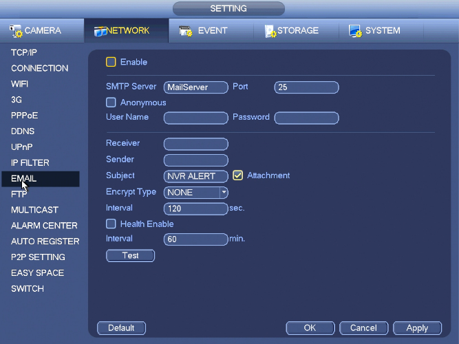
The email interface is shown as above.
- SMTP server: Please input your email SMTP server IP here.
- Port: Please input corresponding port value here.
- User name: Please input the user name to login the sender email box.
- Password: Please input the corresponding password here.
- Sender: Please input sender email box here.
- Title: Please input email subject here. System support English character and Arabic number. Max 32-digit.
- Receiver: Please input receiver email address here. System max supports 3 email boxes. System automatically filters same addresses if you input one receiver repeatedly.
- SSL enable: System supports SSL encryption box.
- Interval: The send interval ranges from 0 to 3600 seconds. 0 means there is no interval.
- Health email enable: Please check the box here to enable this function. This function allows the system to send out the test email to check the connection is OK or not.
- Interval: Please check the above box to enable this function and then set the corresponding interval. System can send out the email regularly as you set here. Click the Test button, you can see the corresponding dialogue box to see the email connection is OK or not.
Please note system will not send out the email immediately when the alarm occurs. When the alarm, motion detection or the abnormity event activates the email, system sends out the email according to the interval you specified here. This function is very useful when there are too many emails activated by the abnormity events, which may result in heavy load for the email server.
FTP
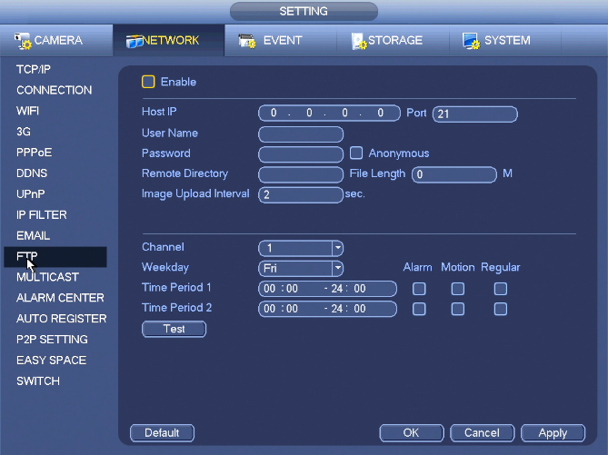
You need to download or buy FTP service tool (such as Ser-U FTP SERVER) to establish FTP service. Please install Ser-U FTP SERVER first. From “start” -> “program” -> Serv-U FTP Server -> Serv-U Administator. Now you can set user password and FTP folder. Please note you need to grant write right to FTP upload user.
You can use a PC or FTP login tool to test setup is right or not. For example, you can login user ZHY to H140H140H140HTUFTP://10.10.7.7UTH and then test it can modify or delete folder or not.
System also supports upload multiple NVRs to one FTP server. You can create multiple folders under this FTP.
Please highlight the icon in front of Enable to activate FTP function. Here you can input FTP server address, port and remote directory. When remote directory is null, system automatically create folders according to the IP, time and channel. User name and password is the account information for you to login the FTP. File length is upload file length. When setup is larger than the actual file length, system will upload the whole file. When setup here is smaller than the actual file length, system only uploads the set length and auto ignore the left section. When interval value is 0, system uploads all corresponding files. After completed channel and weekday setup, you can set two periods for one each channel. Click the Test button, you can see the corresponding dialogue box to see the FTP connection is OK or not.
Multicast
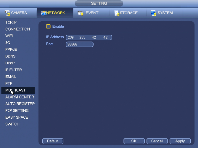
Here you can set a multiple cast group. Please refer to the following sheet for detailed information.
- IP multiple cast group address
-224.0.0.0-239.255.255.255
-“D” address space
- The higher four-bit of the first byte=”1110”
- Reserved local multiple cast group address
-224.0.0.0-224.0.0.255
-TTL=1 When sending out telegraph
-For example
- All systems in the sub-net
- All routers in the sub-net
- DVMRP router
- OSPF router
224.0.0.13 PIMv2 router
- Administrative scoped addressees
-239.0.0.0-239.255.255.255
-Private address space
- Like the single broadcast address of RFC1918
- Can not be used in Internet transmission
- Used for multiple cast broadcast in limited space.
Except the above mentioned addresses of special meaning, you can use other addresses. For example:
Multiple cast IP: 235.8.8.36
Multiple cast PORT: 3666.
After you logged in the Web, the Web can automatically get multiple cast address and add it to the multiple cast groups. You can enable real-time monitor function to view the view.
Please note multiple cast function applies to special series only.
Alarm Center
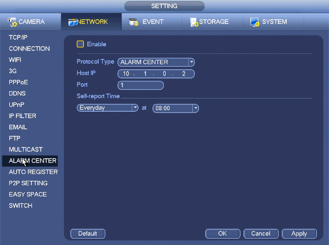
This interface is reserved for you to develop.
Auto Register
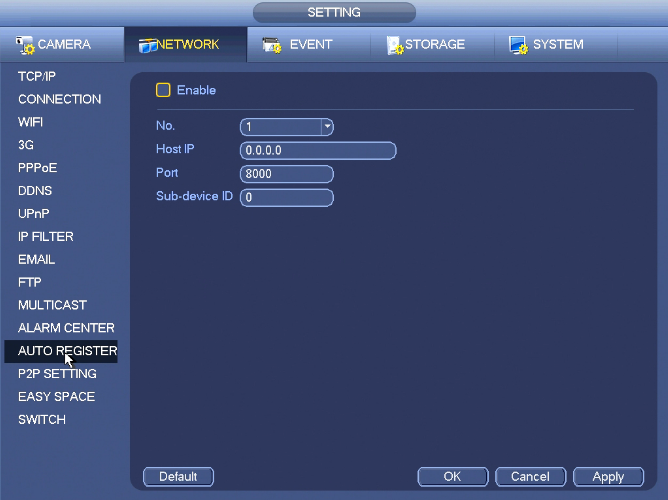
This function allows the device to auto register to the proxy you specified. In this way, you can use the client-end to access the NVR and etc via the proxy. Here the proxy has a switch function. In the network service, device supports the server address of IPv4 or domain.
Please follow the steps listed below to use this function.
Please set proxy server address, port, and sub-device name at the device-end. Please enable the auto register function, the device can auto register to the proxy server.
Important
Do not input network default port such as TCP port number.
1) The proxy server software developed from the SDK. Please open the software and input the global setup. Please make sure the auto connection port here is the same as the port you set in the previous step.
2) Now you can add device. Please do not input default port number such as the TCP port in the mapping port number. The device ID here shall be the same with the ID you input previously. Click Add button to complete the setup.
3) Now you can boot up the proxy server. When you see the network status is Y, it means your registration is OK. You can view the proxy server when the device is online.
Important
The server IP address can also be domain. But you need to register a domain name before you run proxy device server.
P2P Setting
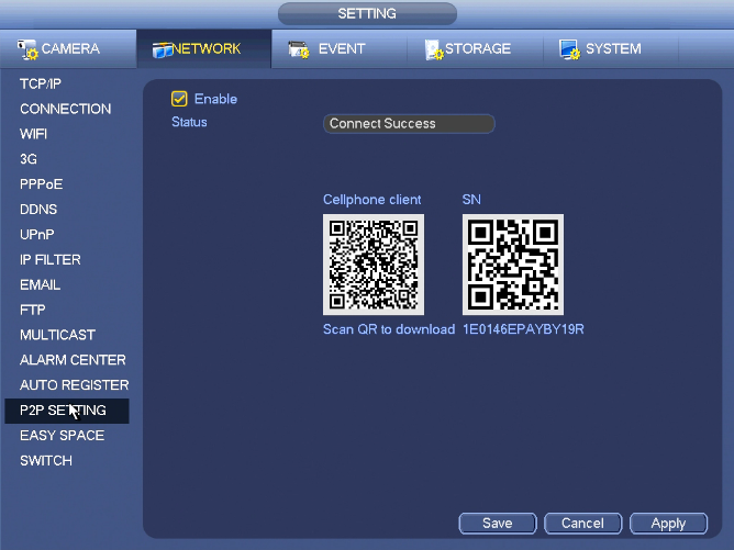
The P2P interface is shown in the above image. You can visit www.easy4ip.com to scan the QR code to login.
Easy Space
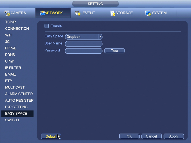
This function allows you to upload motion detec record or snapshot image to the dropbox and etc.
The easy space interface is shown above.
Please select the easy space address from the dropdown list and then input corresponding user name and password.
Note
- The uploaded file is for sub stream only. Please go to record control interface (main stream->setting->Storage->Record) and then select sub stream.
- The easy space function uses upload bandwidth. Usually the recommended upload bandwidth shall be more than 512kbps and please make sure the network is stable.
- The easy space upload data adopts safe SSL encryption connection. Please enable 1-channel to upload in case this function occupies too much CPU.
Switch
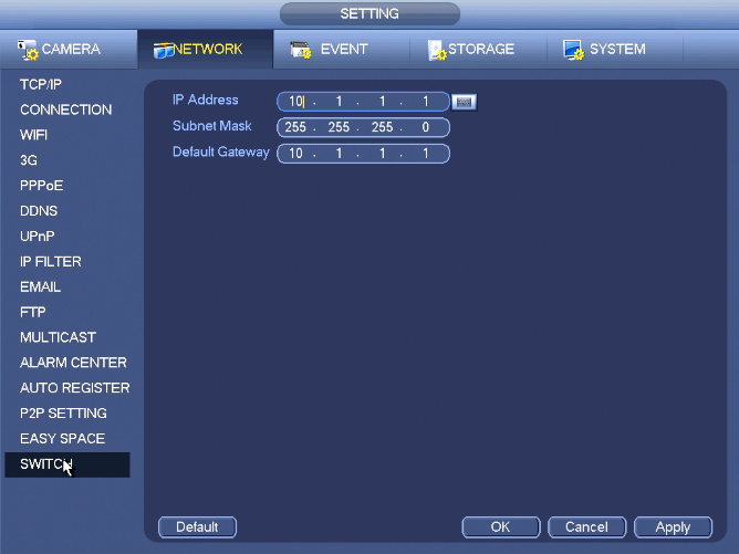
The built-in switch function is for product of PoE port.
It is for you to set IP address, subnet mask, gateway and etc of the Switch.
From Main menu->Setting->Network->Switch, you can set switch IP address, subnet mask, gateway and etc.
