Difference between revisions of "NVRiSettingEvent"
(→IPC Ext) |
|||
| (13 intermediate revisions by 3 users not shown) | |||
| Line 1: | Line 1: | ||
==NVR Interface-Setting-Event== | ==NVR Interface-Setting-Event== | ||
| − | + | <imagemap> | |
| + | Image:NVRiSettingEvent.png | ||
| + | rect 0 25 122 60 [[NVRiSettingCamera]] | ||
| + | rect 122 26 246 60 [[NVRiSettingNetwork]] | ||
| + | rect 248 27 369 61 [[NVRiSettingEvent]] | ||
| + | rect 370 27 492 61 [[NVRiSettingStorage]] | ||
| + | rect 493 27 616 61 [[NVRiSettingSystem]] | ||
| + | desc none | ||
| + | </imagemap> | ||
===Video Detect=== | ===Video Detect=== | ||
[[file:NVRiSettingEventVideoDetect.png]] | [[file:NVRiSettingEventVideoDetect.png]] | ||
| + | |||
====Motion Detect==== | ====Motion Detect==== | ||
[[file:NVRiSettingEventVideoDetectMotionDetect.png]] | [[file:NVRiSettingEventVideoDetectMotionDetect.png]] | ||
| + | |||
| + | ======Motion Detect====== | ||
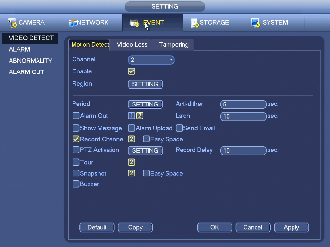
| + | After analysis video, system can generate a motion detect alarm when the detected moving signal reached the sensitivity you set here. | ||
| + | |||
| + | Detection menu is shown as below. | ||
| + | |||
| + | * Event type: From the dropdown list you can select motion detection type. | ||
| + | * Channel: Select a channel from the dropdown list to set motion detect function. | ||
| + | * Enable: Check the box here to enable motion detect function. | ||
| + | * Region: Click select button, Here you can set motion detection zone. There are four zones for you to set. Please select a zone first and then left drag the mouse to select a zone. The corresponding color zone displays different detection zone. You can click Fn button to switch between the arm mode and disarm mode. In arm mode, you can click the direction buttons to move the green rectangle to set the motion detection zone. After you completed the setup, please click ENTER button to exit current setup. Do remember click save button to save current setup. If you click ESC button to exit the region setup interface system will not save your zone setup. | ||
| + | * Sensitivity: System supports 6 levels. The sixth level has the highest sensitivity. | ||
| + | * Anti-dither (AKA Cool Down Time between the next event): Here you can set anti-dither time. The value ranges from 5 to 600s. The anti-dither time refers to the alarm signal lasts time. It can be seem as the alarm signal activation stays such as the buzzer, tour, PTZ activation, snapshot, channel record. The stay time here does not include the latch time. During the alarm process, the alarm signal can begin an anti-dither time if system detects the local alarm again. The screen prompt, alarm upload, email and etc will not be activated. For example, if you set the anti-dither time as 10 second, you can see the each activation may last 10s if the local alarm is activated. During the process, if system detects another local alarm signal at the fifth second, the buzzer, tour, PTZ activation, snapshot, record channel will begin another 10s while the screen prompt, alarm upload, email will not be activated again. After 10s, if system detects another alarm signal, it can generate an alarm since the anti-dither time is out. | ||
| + | * Period: Click set button. Here you can set motion detect period. System only enables motion detect operation in the specified periods. It is not for video loss or the tampering. There are two ways for you to set periods. Please note system only supports 6 periods in one day. | ||
| + | * Select icon of several dates, all checked items can be edited together. Now the icon is shown as. Click to delete a record type from one period. | ||
| + | * Click button after one date or a holiday, you can see an interface shown as in Figure 4‑85. There are four record types: regular, motion detection (MD), Alarm, MD & alarm. | ||
| + | * Alarm output: when an alarm occurs, system enables peripheral alarm devices. | ||
| + | * Latch: when motion detection complete, system auto delays detecting for a specified time. The value ranges from 1-300(Unit: second) | ||
| + | * Show message: System can pop up a message to alarm you in the local host screen if you enabled this function. | ||
| + | * Alarm upload: System can upload the alarm signal to the network (including alarm centre) if you enabled current function. | ||
| + | * Send email: System can send out email to alert you when an alarm occurs. | ||
| + | * Record channel: System auto activates motion detection channel(s) to record once an alarm occurs. Please make sure you have set MD record in Schedule interface(Main Menu->Setting->Schedule) and schedule record in manual record interface(Main Menu->Advanced->Manual Record) | ||
| + | * PTZ activation: Here you can set PTZ movement when an alarm occurs. Such as go to preset, tour &pattern when there is an alarm. Click “select” button. | ||
| + | * Record Delay: System can delay the record for specified time after alarm ended. The value ranges from 10s to 300s. | ||
| + | * Tour: Here you can enable tour function when alarm occurs. System one-window tour. | ||
| + | * Snapshot: You can enable this function to snapshoot image when a motion detect alarm occurs. | ||
| + | * Video matrix Check the box here to enable this function. When an alarm occurs, SPOT OUT port displays device video output. It displays video (1-window tour) from alarm activation channel you select at the Record channel item. | ||
| + | * Buzzer: Highlight the icon to enable this function. The buzzer beeps when alarm occurs. | ||
| + | |||
| + | Please highlight icon to select the corresponding function. After all the setups please click save button, system goes back to the previous menu. | ||
| + | |||
| + | '''Note:''' | ||
| + | |||
| + | In motion detection mode, you can not use copy/paste to set channel setup since the video in each channel may not be the same. | ||
| + | |||
| + | You can left click mouse and then drag it to set a region for motion detection. Click Fn to switch between arm/withdraw motion detection. After setting, click enter button to exit. | ||
| + | |||
====Video Loss==== | ====Video Loss==== | ||
[[file:NVRiSettingEventVideoDetectVideoLoss.png]] | [[file:NVRiSettingEventVideoDetectVideoLoss.png]] | ||
| + | |||
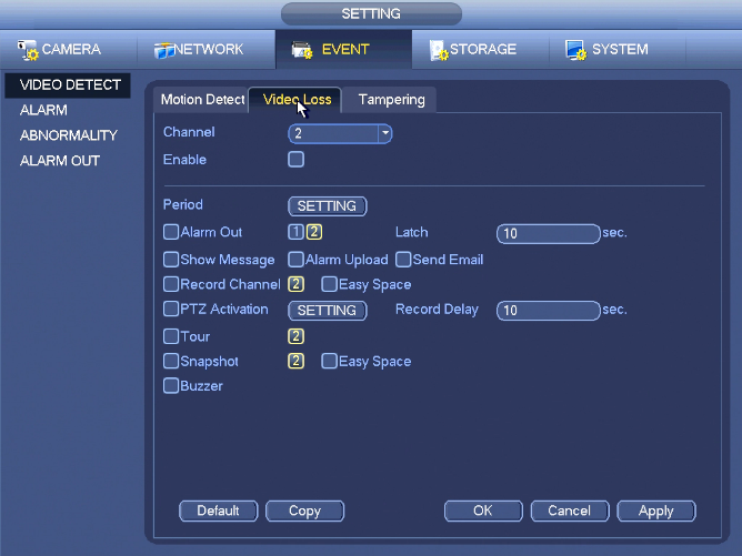
| + | In this section, you can select what actions the system will take when the video feed is lost from one or multiple channels. | ||
| + | |||
| + | This function allows you to be informed when video loss phenomenon occurred. | ||
| + | |||
| + | You can enable alarm output channel and then enable show message function. | ||
| + | |||
| + | '''Tips:''' | ||
| + | |||
| + | You can enable preset/tour/pattern activation operation when video loss occurs. | ||
| + | |||
====Tampering==== | ====Tampering==== | ||
[[file:NVRiSettingEventVideoDetectTampering.png]] | [[file:NVRiSettingEventVideoDetectTampering.png]] | ||
| + | |||
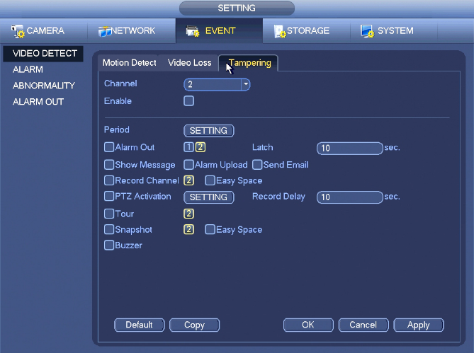
| + | When someone viciously masks the lens, or the output video is in one-color due to the environments light change, the system can alert you to guarantee video continuity. You can enable “Alarm output “or “Show message” function when tampering alarm occurs. | ||
| + | |||
| + | * Sensitivity: The value ranges from 1 to 6. It mainly concerns the brightness. The level 6 has the higher sensitivity than level 1. The default setup is 3. | ||
| + | |||
| + | '''Tips:''' | ||
| + | |||
| + | You can enable preset/tour/pattern activation operation when video loss occurs. | ||
| + | |||
| + | '''Note:''' | ||
| + | |||
| + | * In Detect interface, copy/paste function is only valid for the same type, which means you can not copy a channel setup in video loss mode to tampering | ||
| + | * About Default function. Since detection channel and detection type may not be the same, system can only restore default setup of current detect type. For example, if you click Default button at the tampering interface, you can only restore default tampering It is null for other detect types. | ||
| + | * System only enables tampering function during the period you set here. It is null for motion detect or video loss type. | ||
===Alarm=== | ===Alarm=== | ||
[[file:NVRiSettingEventAlarm.png]] | [[file:NVRiSettingEventAlarm.png]] | ||
| + | |||
====IPC Ext==== | ====IPC Ext==== | ||
[[file:NVRiSettingEventAlarmIPCExt.png]] | [[file:NVRiSettingEventAlarmIPCExt.png]] | ||
| Line 35: | Line 106: | ||
# Click Copy button to copy current setup to other channel(s). | # Click Copy button to copy current setup to other channel(s). | ||
# Click OK button to save alarm record information. | # Click OK button to save alarm record information. | ||
| + | |||
| + | '''Important ''' | ||
| + | |||
| + | * '''If it is your first time to boot up the device, the disconnection status of the front-end network camera will not be regarded as offline. After one successfully connection, all the disconnection events will be regarded as IPC offline event. ''' | ||
| + | * '''When IPC offline alarm occurs, the record and snapshot function of digital channel is null. ''' | ||
| + | |||
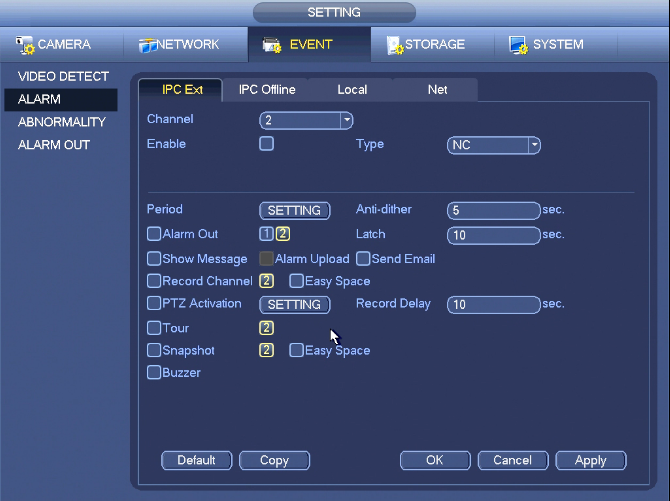
| + | * Enable: Please you need to highlight this button to enable current function. | ||
| + | * Type: normal open or normal close. | ||
| + | * Period: Click set button, you can see an interface is shown as in Figure 4‑94. There are two ways for you to set periods. There are max 6 periods in one day. There are four record types: regular, motion detection (MD), Alarm, MD & alarm. | ||
| + | ** Select icon[[File:SelectIcon.png]] of several dates, all checked items can be edited together. Now the icon is shown as[[File:SyncIconO.png]]. Click [[file:EraseIcon.png]] to delete a record type from one period. | ||
| + | ** Click button [[File:GearIcon.png]] after one date or a holiday. There are four record types: regular, motion detection (MD), Alarm, MD & alarm. | ||
| + | * PTZ activation: When an alarm occurred, system can activate the PTZ operation. The PTZ activation lasts an anti-dither period. | ||
| + | * Anti-dither: Here you can set anti-dither time. The value ranges from 5 to 600s. The anti-dither time refers to the alarm signal lasts time. It can be seem as the alarm signal activation stays such as the buzzer, tour, PTZ activation, snapshot, channel record. The stay time here does not include the latch time. During the alarm process, the alarm signal can begin an anti-dither time if system detects the local alarm again. The screen prompt, alarm upload, email and etc will not be activated. For example, if you set the anti-dither time as 10 second, you can see the each activation may last 10s if the local alarm is activated. During the process, if system detects another local alarm signal at the fifth second, the buzzer, tour, PTZ activation, snapshot, record channel will begin another 10s while the screen prompt, alarm upload, email will not be activated again. After 10s, if system detects another alarm signal, it can generate an alarm since the anti-dither time is out. | ||
| + | * Alarm output: The number here is the device alarm output port. You can select the corresponding ports(s) so that system can activate the corresponding alarm device(s) when an alarm occurred. | ||
| + | * Latch: When the anti-dither time ended, the channel alarm you select in the alarm output may last the specified period. The value ranges from 1 to 300 seconds. This function is not for other alarm activation operations. The latch is still valid even you disable the alarm event function directly. | ||
| + | * Show message: System can pop up a message to alarm you in the local host screen if you enabled this function. | ||
| + | * Alarm upload: System can upload the alarm signal to the network (including alarm centre and the WEB) if you enabled current function. System only uploads the alarm channel status. You can go to the WEB and then go to the Alarm interface to set alarm event and alarm operation. Please go to the Network interface to set alarm centre information. | ||
| + | * Send email: System can send out the alarm signal via the email to alert you when alarm occurs. Once you enable the snap function, system can also send out an image as the attachment. Please go to the Main Menu->Setting ->Network->Email interface to set. | ||
| + | * Record channel: you can select proper channel to record alarm video (Multiple choices). | ||
| + | ** You need to set alarm record mode as Schedule in Record interface (Main Menu->Advanced->Record). Please note the manual record has the highest priority. System record all the time no matter there is an alarm or not if you select Manual mode. | ||
| + | ** Now you can go to the Schedule interface (Main Menu->Setting->Schedule) to set the record type, corresponding channel number, week and date. You can select the record type:Regular/MD/Alarm/MD&Alarm. Please note, you can not select the MD&Alarm and MD(or Alarm) at the same time. | ||
| + | ** Now you can go to the Encode interface to select the alarm record and set the encode parameter (Main Menu->Setting->Encode). | ||
| + | ** Finally, you can set the alarm input as the local alarm and then select the record channel. The select channel begins alarm record when an alarm occurred. Please note system begins the alarm record instead of the MD record if the local alarm and MD event occurred at the same time. | ||
| + | * Tour: Here you can enable tour function when an alarm occurs. System supports 1/8-window tour. Display for tour interval setup. Please note the tour setup here has higher priority than the tour setup you set in the Display interface. Once there two tours are both enabled, system can enable the alarm tour as you set here when an alarm occurred. If there is no alarm, system implements the tour setup in the Display interface. | ||
| + | * Snapshot: You can enable this function to snapshoot image when an alarm occurs. | ||
| + | * Buzzer: Highlight the icon to enable this function. The buzzer beeps when an alarm occurs. | ||
=====Alarm Snapshot===== | =====Alarm Snapshot===== | ||
| Line 43: | Line 140: | ||
====IPC Offline==== | ====IPC Offline==== | ||
[[file:NVRiSettingEventAlarmIPCOffline.png]] | [[file:NVRiSettingEventAlarmIPCOffline.png]] | ||
| + | |||
====Local==== | ====Local==== | ||
[[file:NVRiSettingEventAlarmLocal.png]] | [[file:NVRiSettingEventAlarmLocal.png]] | ||
| + | |||
====Net==== | ====Net==== | ||
[[file:NVRiSettingEventAlarmNet.png]] | [[file:NVRiSettingEventAlarmNet.png]] | ||
| Line 50: | Line 149: | ||
===Abnormality=== | ===Abnormality=== | ||
[[file:NVRiSettingEventAbnormality.png]] | [[file:NVRiSettingEventAbnormality.png]] | ||
| + | |||
| + | There are two types: Disk/Network. | ||
| + | |||
| + | * Disk: Disk error, no disk, no space. | ||
| + | * Network: Disconnection, IP conflict, MAC conflict. | ||
| + | |||
| + | * Alarm output: Please select alarm activation output port (multiple choices). | ||
| + | * Less than: System can alarm you when the HDD space is less than the threshold you set here (For HDD no space type only). | ||
| + | * Latch: Here you can set corresponding delaying time. The value ranges from 1s-300s. System automatically delays specified seconds in turning off alarm and activated output after external alarm cancelled. | ||
| + | * Show message: system can pop up the message in the local screen to alert you when alarm occurs. | ||
| + | * Alarm upload: System can upload the alarm signal to the network (including alarm centre) if you enabled current function. For disconnection event, IP conflict event and MAC conflict event, this function is null. | ||
| + | * Send email: System can send out email to alert you when alarm occurs. | ||
| + | * Buzzer: Highlight the icon to enable this function. The buzzer beeps when an alarm occurs. | ||
| + | |||
====HDD==== | ====HDD==== | ||
[[file:NVRiSettingEventAbnormalityHDD.png]] | [[file:NVRiSettingEventAbnormalityHDD.png]] | ||
| + | |||
====Network==== | ====Network==== | ||
[[file:NVRiSettingEventAbnormalityNetwork.png]] | [[file:NVRiSettingEventAbnormalityNetwork.png]] | ||
| Line 59: | Line 173: | ||
====Alarm Out==== | ====Alarm Out==== | ||
| + | From Main Menu->Setting->Event->Alarm Output | ||
| + | |||
| + | Here is for you to set proper alarm output (Auto/manual/stop). | ||
| + | |||
| + | Click OK button of the alarm reset, you can clear all alarm output status. | ||
| + | |||
[[file:NVRiSettingEventAlarmOutAlarmOut.png]] | [[file:NVRiSettingEventAlarmOutAlarmOut.png]] | ||
| + | |||
| + | |||
| + | |||
| + | |||
| + | [[Category:NVR Interface]] | ||
Latest revision as of 20:48, 3 December 2020
Contents
NVR Interface-Setting-Event

Video Detect
Motion Detect
Motion Detect
After analysis video, system can generate a motion detect alarm when the detected moving signal reached the sensitivity you set here.
Detection menu is shown as below.
- Event type: From the dropdown list you can select motion detection type.
- Channel: Select a channel from the dropdown list to set motion detect function.
- Enable: Check the box here to enable motion detect function.
- Region: Click select button, Here you can set motion detection zone. There are four zones for you to set. Please select a zone first and then left drag the mouse to select a zone. The corresponding color zone displays different detection zone. You can click Fn button to switch between the arm mode and disarm mode. In arm mode, you can click the direction buttons to move the green rectangle to set the motion detection zone. After you completed the setup, please click ENTER button to exit current setup. Do remember click save button to save current setup. If you click ESC button to exit the region setup interface system will not save your zone setup.
- Sensitivity: System supports 6 levels. The sixth level has the highest sensitivity.
- Anti-dither (AKA Cool Down Time between the next event): Here you can set anti-dither time. The value ranges from 5 to 600s. The anti-dither time refers to the alarm signal lasts time. It can be seem as the alarm signal activation stays such as the buzzer, tour, PTZ activation, snapshot, channel record. The stay time here does not include the latch time. During the alarm process, the alarm signal can begin an anti-dither time if system detects the local alarm again. The screen prompt, alarm upload, email and etc will not be activated. For example, if you set the anti-dither time as 10 second, you can see the each activation may last 10s if the local alarm is activated. During the process, if system detects another local alarm signal at the fifth second, the buzzer, tour, PTZ activation, snapshot, record channel will begin another 10s while the screen prompt, alarm upload, email will not be activated again. After 10s, if system detects another alarm signal, it can generate an alarm since the anti-dither time is out.
- Period: Click set button. Here you can set motion detect period. System only enables motion detect operation in the specified periods. It is not for video loss or the tampering. There are two ways for you to set periods. Please note system only supports 6 periods in one day.
- Select icon of several dates, all checked items can be edited together. Now the icon is shown as. Click to delete a record type from one period.
- Click button after one date or a holiday, you can see an interface shown as in Figure 4‑85. There are four record types: regular, motion detection (MD), Alarm, MD & alarm.
- Alarm output: when an alarm occurs, system enables peripheral alarm devices.
- Latch: when motion detection complete, system auto delays detecting for a specified time. The value ranges from 1-300(Unit: second)
- Show message: System can pop up a message to alarm you in the local host screen if you enabled this function.
- Alarm upload: System can upload the alarm signal to the network (including alarm centre) if you enabled current function.
- Send email: System can send out email to alert you when an alarm occurs.
- Record channel: System auto activates motion detection channel(s) to record once an alarm occurs. Please make sure you have set MD record in Schedule interface(Main Menu->Setting->Schedule) and schedule record in manual record interface(Main Menu->Advanced->Manual Record)
- PTZ activation: Here you can set PTZ movement when an alarm occurs. Such as go to preset, tour &pattern when there is an alarm. Click “select” button.
- Record Delay: System can delay the record for specified time after alarm ended. The value ranges from 10s to 300s.
- Tour: Here you can enable tour function when alarm occurs. System one-window tour.
- Snapshot: You can enable this function to snapshoot image when a motion detect alarm occurs.
- Video matrix Check the box here to enable this function. When an alarm occurs, SPOT OUT port displays device video output. It displays video (1-window tour) from alarm activation channel you select at the Record channel item.
- Buzzer: Highlight the icon to enable this function. The buzzer beeps when alarm occurs.
Please highlight icon to select the corresponding function. After all the setups please click save button, system goes back to the previous menu.
Note:
In motion detection mode, you can not use copy/paste to set channel setup since the video in each channel may not be the same.
You can left click mouse and then drag it to set a region for motion detection. Click Fn to switch between arm/withdraw motion detection. After setting, click enter button to exit.
Video Loss
In this section, you can select what actions the system will take when the video feed is lost from one or multiple channels.
This function allows you to be informed when video loss phenomenon occurred.
You can enable alarm output channel and then enable show message function.
Tips:
You can enable preset/tour/pattern activation operation when video loss occurs.
Tampering
When someone viciously masks the lens, or the output video is in one-color due to the environments light change, the system can alert you to guarantee video continuity. You can enable “Alarm output “or “Show message” function when tampering alarm occurs.
- Sensitivity: The value ranges from 1 to 6. It mainly concerns the brightness. The level 6 has the higher sensitivity than level 1. The default setup is 3.
Tips:
You can enable preset/tour/pattern activation operation when video loss occurs.
Note:
- In Detect interface, copy/paste function is only valid for the same type, which means you can not copy a channel setup in video loss mode to tampering
- About Default function. Since detection channel and detection type may not be the same, system can only restore default setup of current detect type. For example, if you click Default button at the tampering interface, you can only restore default tampering It is null for other detect types.
- System only enables tampering function during the period you set here. It is null for motion detect or video loss type.
Alarm
IPC Ext
Alarm Record
- Before you set alarm setup information, please connect alarm input and alarm output cable (such as light, siren and etc).
- The record priority is: Alarm>Motion>Regular
In the main menu, from Setting->Event-> Alarm, you can see alarm setup interface.
- Alarm in: Here is for you to select channel number.
- Event type: There are four types. Local input/network input/IPC external/IPC offline alarm.
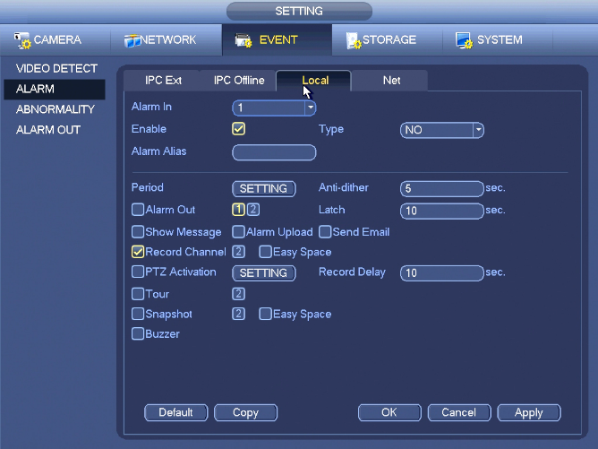
- Local input alarm: The alarm signal system detects from the alarm input port.
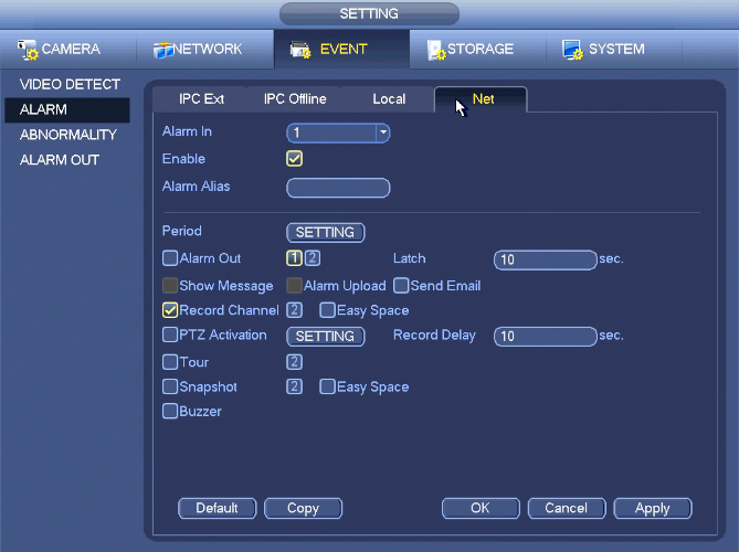
- Network input alarm: It is the alarm signal from the network.
- IPC external alarm: It is the on-off alarm signal from the front-end device and can activate the local NVR.
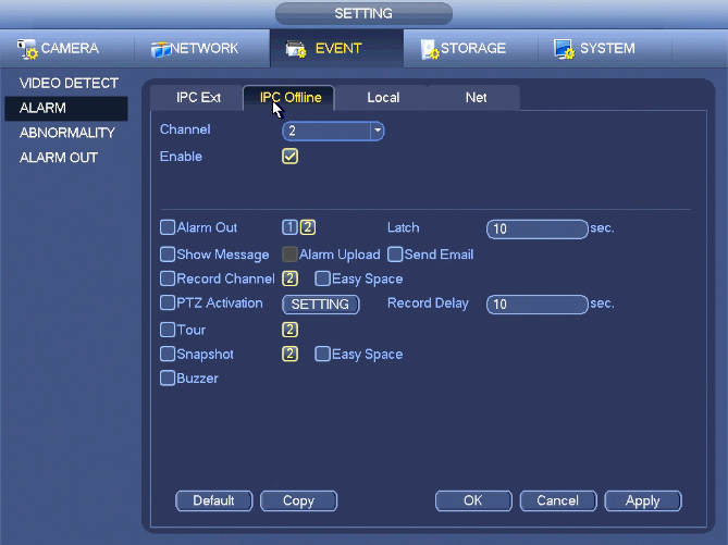
- IPC offline alarm: Once you select this item, system can generate an alarm when the front-end IPC disconnects with the local NVR. The alarm can activate record, PTZ, snapshot and etc. The alarm can last until the IPC and the NVR connection resumes.
- Enable: Please you need to highlight this button to enable current function.
- Type: normal open or normal close.
- Click Save button to complete alarm setup interface.
- From Main Menu->Setting->Storage->Schedule
- Select alarm channel, period and the record type shall be alarm.
- Click Copy button to copy current setup to other channel(s).
- Click OK button to save alarm record information.
Important
- If it is your first time to boot up the device, the disconnection status of the front-end network camera will not be regarded as offline. After one successfully connection, all the disconnection events will be regarded as IPC offline event.
- When IPC offline alarm occurs, the record and snapshot function of digital channel is null.
- Enable: Please you need to highlight this button to enable current function.
- Type: normal open or normal close.
- Period: Click set button, you can see an interface is shown as in Figure 4‑94. There are two ways for you to set periods. There are max 6 periods in one day. There are four record types: regular, motion detection (MD), Alarm, MD & alarm.
- PTZ activation: When an alarm occurred, system can activate the PTZ operation. The PTZ activation lasts an anti-dither period.
- Anti-dither: Here you can set anti-dither time. The value ranges from 5 to 600s. The anti-dither time refers to the alarm signal lasts time. It can be seem as the alarm signal activation stays such as the buzzer, tour, PTZ activation, snapshot, channel record. The stay time here does not include the latch time. During the alarm process, the alarm signal can begin an anti-dither time if system detects the local alarm again. The screen prompt, alarm upload, email and etc will not be activated. For example, if you set the anti-dither time as 10 second, you can see the each activation may last 10s if the local alarm is activated. During the process, if system detects another local alarm signal at the fifth second, the buzzer, tour, PTZ activation, snapshot, record channel will begin another 10s while the screen prompt, alarm upload, email will not be activated again. After 10s, if system detects another alarm signal, it can generate an alarm since the anti-dither time is out.
- Alarm output: The number here is the device alarm output port. You can select the corresponding ports(s) so that system can activate the corresponding alarm device(s) when an alarm occurred.
- Latch: When the anti-dither time ended, the channel alarm you select in the alarm output may last the specified period. The value ranges from 1 to 300 seconds. This function is not for other alarm activation operations. The latch is still valid even you disable the alarm event function directly.
- Show message: System can pop up a message to alarm you in the local host screen if you enabled this function.
- Alarm upload: System can upload the alarm signal to the network (including alarm centre and the WEB) if you enabled current function. System only uploads the alarm channel status. You can go to the WEB and then go to the Alarm interface to set alarm event and alarm operation. Please go to the Network interface to set alarm centre information.
- Send email: System can send out the alarm signal via the email to alert you when alarm occurs. Once you enable the snap function, system can also send out an image as the attachment. Please go to the Main Menu->Setting ->Network->Email interface to set.
- Record channel: you can select proper channel to record alarm video (Multiple choices).
- You need to set alarm record mode as Schedule in Record interface (Main Menu->Advanced->Record). Please note the manual record has the highest priority. System record all the time no matter there is an alarm or not if you select Manual mode.
- Now you can go to the Schedule interface (Main Menu->Setting->Schedule) to set the record type, corresponding channel number, week and date. You can select the record type:Regular/MD/Alarm/MD&Alarm. Please note, you can not select the MD&Alarm and MD(or Alarm) at the same time.
- Now you can go to the Encode interface to select the alarm record and set the encode parameter (Main Menu->Setting->Encode).
- Finally, you can set the alarm input as the local alarm and then select the record channel. The select channel begins alarm record when an alarm occurred. Please note system begins the alarm record instead of the MD record if the local alarm and MD event occurred at the same time.
- Tour: Here you can enable tour function when an alarm occurs. System supports 1/8-window tour. Display for tour interval setup. Please note the tour setup here has higher priority than the tour setup you set in the Display interface. Once there two tours are both enabled, system can enable the alarm tour as you set here when an alarm occurred. If there is no alarm, system implements the tour setup in the Display interface.
- Snapshot: You can enable this function to snapshoot image when an alarm occurs.
- Buzzer: Highlight the icon to enable this function. The buzzer beeps when an alarm occurs.
Alarm Snapshot
- From Main menu->Setting->Storage->schedule to enable snapshot function.
- From Main menu->Setting->Event->Alarm, you can go to Figure 4‑65 to set alarm parameter and enable snapshot function.
- Click Save button to save alarm snapshot setup.
IPC Offline
Local
Net
Abnormality
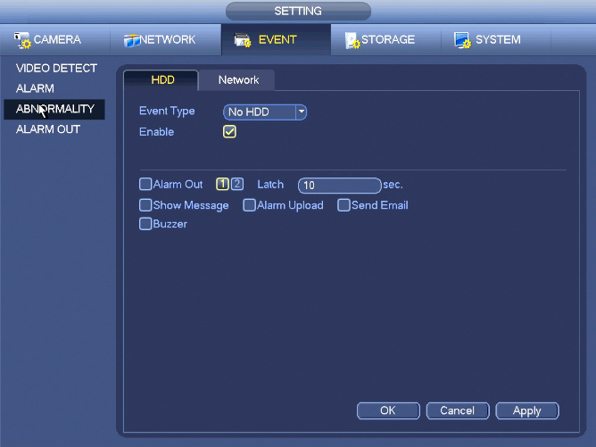
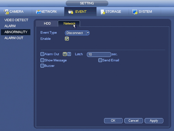
There are two types: Disk/Network.
- Disk: Disk error, no disk, no space.
- Network: Disconnection, IP conflict, MAC conflict.
- Alarm output: Please select alarm activation output port (multiple choices).
- Less than: System can alarm you when the HDD space is less than the threshold you set here (For HDD no space type only).
- Latch: Here you can set corresponding delaying time. The value ranges from 1s-300s. System automatically delays specified seconds in turning off alarm and activated output after external alarm cancelled.
- Show message: system can pop up the message in the local screen to alert you when alarm occurs.
- Alarm upload: System can upload the alarm signal to the network (including alarm centre) if you enabled current function. For disconnection event, IP conflict event and MAC conflict event, this function is null.
- Send email: System can send out email to alert you when alarm occurs.
- Buzzer: Highlight the icon to enable this function. The buzzer beeps when an alarm occurs.
HDD
Network
Alarm Out
Alarm Out
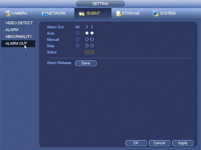
From Main Menu->Setting->Event->Alarm Output
Here is for you to set proper alarm output (Auto/manual/stop).
Click OK button of the alarm reset, you can clear all alarm output status.

