Difference between revisions of "Thermal/DHI-ASI7213X-T1/Instructions/Alarm Input and Output"
| (71 intermediate revisions by 3 users not shown) | |||
| Line 1: | Line 1: | ||
=Alarm Input and Output= | =Alarm Input and Output= | ||
| + | [[file:DHI-ASI7213X-T1_Cable_Connections.png|thumb|Cable Connections]] | ||
| + | [[file:DHI-ASI7213X-T1_Physical_Setup.png|thumb|Physical Setup]] | ||
| + | |||
| + | |||
| + | {| class="wikitable" | ||
| + | ! style="text-align:center;"|[https://dahuawiki.com/index.php?action=ajax&title=-&rs=SecureFileStore::getFile&f=/c/c7/DHI-ASI7213X-T1_Contacts_Print_Sheet.xlsx <ul class="fa-ul"><li><i class="fas fa-file-pdf fa-4x" style="color:darkred;></i></li></ul>]DHI-ASI7213X-T1 Contacts Reference Sheet | ||
| + | |} | ||
| + | |||
| + | ==Web Interface== | ||
| + | <gallery> | ||
| + | File:DHI-ASI7213X-T1_Alarm_Linkage_WebUI.png|''Alarm Linkage'' | ||
| + | File:DHI-ASI7213X-T1_Alarm_Linkage_Log_WebUI.png|''Alarm Linkage Log'' | ||
| + | File:DHI-ASI7213X-T1_Alarm_Linkage_Modify_WebUI.png|''Alarm Linkage-Modify'' | ||
| + | </gallery> | ||
| + | |||
==Cable Connections== | ==Cable Connections== | ||
| + | *Alarm1 = High Temp | ||
| + | *Alarm2 = Normal Temp or No Mask | ||
| + | *No alert for face detection currently. | ||
| + | |||
===Contact 1=== | ===Contact 1=== | ||
{| class="wikitable" | {| class="wikitable" | ||
!|Port | !|Port | ||
| − | !|Cable Color | + | !colspan="2"|Cable Color |
!|Cable Name | !|Cable Name | ||
!|Description | !|Description | ||
| Line 13: | Line 32: | ||
|- | |- | ||
|Black | |Black | ||
| + | |[[File:Wire_black.svg|35px]] | ||
|RD– | |RD– | ||
|Negative electrode of external card reader. | |Negative electrode of external card reader. | ||
|- | |- | ||
|Red | |Red | ||
| + | |[[File:Wire_red.svg|35px]] | ||
|RD+ | |RD+ | ||
|Positive electrode of external card reader. | |Positive electrode of external card reader. | ||
|- | |- | ||
| − | |Blue | + | |Blue |
| + | |[[File:Wire_blue.svg|35px]] | ||
|CASE | |CASE | ||
|Tamper alarm input of the external card reader. | |Tamper alarm input of the external card reader. | ||
|- | |- | ||
|White | |White | ||
| + | |[[File:Wire_white.svg|35px]] | ||
|D1 | |D1 | ||
|Wiegand D1 input (connected to external card reader)/output (connected to controller). | |Wiegand D1 input (connected to external card reader)/output (connected to controller). | ||
|- | |- | ||
|Green | |Green | ||
| + | |[[File:Wire_green.svg|35px]] | ||
|D0 | |D0 | ||
|Wiegand D0 input (connected to external card reader)/output (connected to controller). | |Wiegand D0 input (connected to external card reader)/output (connected to controller). | ||
|- | |- | ||
|Brown | |Brown | ||
| + | |[[File:Wire_brown.svg|35px]] | ||
|LED | |LED | ||
|Connected to external reader indicator in | |Connected to external reader indicator in | ||
|- | |- | ||
|Yellow | |Yellow | ||
| + | |[[File:Wire_yellow.svg|35px]] | ||
|B | |B | ||
|RS-485 negative electrode input (connected to external card reader)/output (connected to controller, or connected to door control security module). | |RS-485 negative electrode input (connected to external card reader)/output (connected to controller, or connected to door control security module). | ||
| Line 43: | Line 69: | ||
|- | |- | ||
|Purple | |Purple | ||
| + | |[[File:Wire_purple.png|35px]] | ||
|A | |A | ||
|RS-485 positive electrode input (connected to external card reader)/output (connected to controller, or connected to door control security module). | |RS-485 positive electrode input (connected to external card reader)/output (connected to controller, or connected to door control security module). | ||
| Line 52: | Line 79: | ||
{| class="wikitable" | {| class="wikitable" | ||
!|Port | !|Port | ||
| − | !|Cable Color | + | !colspan="2"|Cable Color |
!|Cable Name | !|Cable Name | ||
!|Description | !|Description | ||
| Line 61: | Line 88: | ||
|- | |- | ||
|White and red | |White and red | ||
| + | |[[File:Wire_white_red_stripe.svg|35px]] | ||
|ALARM1_NO | |ALARM1_NO | ||
|Alarm 1 normally open output port | |Alarm 1 normally open output port | ||
|- | |- | ||
|White and orange | |White and orange | ||
| + | |[[File:Wire_white_orange_stripe.svg|35px]] | ||
|ALARM1_COM | |ALARM1_COM | ||
|Alarm 1 common output port. | |Alarm 1 common output port. | ||
|- | |- | ||
|White and blue | |White and blue | ||
| + | |[[File:Wire_white_blue_stripe.svg|35px]] | ||
|ALARM2_NO | |ALARM2_NO | ||
|Alarm 2 normally open output port. | |Alarm 2 normally open output port. | ||
|- | |- | ||
|White and gray | |White and gray | ||
| + | |[[File:Wire_white_gray_stripe.svg|35px]] | ||
|ALARM2_COM | |ALARM2_COM | ||
|Alarm 2 common output port. | |Alarm 2 common output port. | ||
|- | |- | ||
|White and green | |White and green | ||
| + | |[[File:Wire_white_green_stripe.svg|35px]] | ||
|GND | |GND | ||
|Connected to the common GND port. | |Connected to the common GND port. | ||
|- | |- | ||
|White Brown | |White Brown | ||
| + | |[[File:Wire_white_brown_stripe.svg|35px]] | ||
|ALARM1 | |ALARM1 | ||
|Alarm 1 input port. | |Alarm 1 input port. | ||
|- | |- | ||
|White and yellow | |White and yellow | ||
| + | |[[File:Wire_white_yellow_stripe.svg|35px]] | ||
|GND | |GND | ||
|Connected to the common GND port. | |Connected to the common GND port. | ||
|- | |- | ||
|White and purple | |White and purple | ||
| + | |[[file:Wire_white_purple_stripe.png|35px]] | ||
|ALARM2 | |ALARM2 | ||
|Alarm 2 input port. | |Alarm 2 input port. | ||
|} | |} | ||
| + | |||
| + | ===Contact 3=== | ||
| + | {| class="wikitable" | ||
| + | !|Port | ||
| + | !colspan="2"|Cable Color | ||
| + | !|Cable Name | ||
| + | !|Description | ||
| + | |- | ||
| + | |+CON3 | ||
| + | |- | ||
| + | |rowspan="9"|CON3 | ||
| + | |- | ||
| + | |Black and blue | ||
| + | |[[File:Wire_black_blue_stripe.svg|35px]] | ||
| + | |GND | ||
| + | |Connected to the common GND port. | ||
| + | |- | ||
| + | |Black and gray | ||
| + | |[[File:Wire_black_gray_stripe.svg|35px]] | ||
| + | |SR1 | ||
| + | |Used for door contact detection. | ||
| + | |- | ||
| + | |Black and green | ||
| + | |[[File:Wire_black_green_stripe.svg|35px]] | ||
| + | |PUSH1 | ||
| + | |Door open button of door No.1 | ||
| + | |- | ||
| + | |Black and brown | ||
| + | |[[File:Wire_black_brown_stripe.svg|35px]] | ||
| + | |DOOR1_COM | ||
| + | |Lock control common port. | ||
| + | |- | ||
| + | |Black and yellow | ||
| + | |[[File:Wire_black_yellow_stripe.svg|35px]] | ||
| + | |DOOR1_NO | ||
| + | |Lock control normally open port. | ||
| + | |- | ||
| + | |Black and purple | ||
| + | |[[File:Wire_black_purple_stripe.png|35px]] | ||
| + | |DOOR1_NC | ||
| + | |Lock control normally closed port. | ||
| + | |} | ||
| + | |||
| + | ==Alarm Outputs 1 and 2 - New Firmware== | ||
| + | |||
| + | {| class="wikitable" | ||
| + | |- | ||
| + | !|PLEASE NOTE: These instructions are for Alarm Outputs 1 and 2 on firmware version 1.000.10BE001.0.R.200722 and later | ||
| + | |- | ||
| + | |} | ||
| + | |||
| + | ===High Body Temperature Indication Light=== | ||
| + | [[File:High Temp Alarm Setup-newfw.png|700px|right]] | ||
| + | {| class="wikitable" | ||
| + | !|Port | ||
| + | !colspan="2"|Cable Color | ||
| + | !|Cable Name | ||
| + | !|Description | ||
| + | |- | ||
| + | |+CON2 | ||
| + | |- | ||
| + | |rowspan="9"|CON2 | ||
| + | |- | ||
| + | |White and red | ||
| + | |[[File:Wire_white_red_stripe.svg|35px]] | ||
| + | |ALARM1_NO | ||
| + | |Alarm 1 normally open output port | ||
| + | |- | ||
| + | |White and orange | ||
| + | |[[File:Wire_white_orange_stripe.svg|35px]] | ||
| + | |ALARM1_COM | ||
| + | |Alarm 1 common output port. | ||
| + | |- | ||
| + | |} | ||
| + | <br><br><br><br><br><br><br><br><br><br><br><br><br><br> | ||
| + | |||
| + | ===Normal Body Temperature or No Mask Indication Light=== | ||
| + | {| class="wikitable" | ||
| + | |- | ||
| + | !|PLEASE NOTE: On firmware version 1.000.10BE001.0.R.200722 and later, you must set the Alarm Output 2 mode setting to either "Normal Temperature Alarm" for being triggered when a normal temperature is detected or "No Mask Alarm" for being triggered when no mask is detected | ||
| + | |- | ||
| + | |[[File:ThermalKioskAlarmOutput2.PNG|600px|center]] | ||
| + | |- | ||
| + | |} | ||
| + | |||
| + | [[File:Normal Temp alarm Setup-newfw.png|700px|right]] | ||
| + | {| class="wikitable" | ||
| + | !|Port | ||
| + | !colspan="2"|Cable Color | ||
| + | !|Cable Name | ||
| + | !|Description | ||
| + | |- | ||
| + | |+CON2 | ||
| + | |- | ||
| + | |rowspan="9"|CON2 | ||
| + | |- | ||
| + | |White and blue | ||
| + | |[[File:Wire_white_blue_stripe.svg|35px]] | ||
| + | |ALARM2_NO | ||
| + | |Alarm 2 normally open output port. | ||
| + | |- | ||
| + | |White and gray | ||
| + | |[[File:Wire_white_gray_stripe.svg|35px]] | ||
| + | |ALARM2_COM | ||
| + | |Alarm 2 common output port. | ||
| + | |} | ||
| + | <br><br><br><br><br><br><br><br><br><br><br><br><br><br> | ||
| + | |||
| + | ==Alarm Outputs 1 and 2 - Old Firmware== | ||
| + | {| class="wikitable" | ||
| + | |- | ||
| + | !|PLEASE NOTE: These instructions are for Alarm Outputs 1 and 2 on firmware older than version 1.000.10BE001.0.R.200722 | ||
| + | |- | ||
| + | |} | ||
| + | |||
| + | ===High Body Temperature Indication Light=== | ||
| + | [[File:High Temp Alarm Setup.png |700px|right]] | ||
| + | {| class="wikitable" | ||
| + | !|Port | ||
| + | !colspan="2"|Cable Color | ||
| + | !|Cable Name | ||
| + | !|Description | ||
| + | |- | ||
| + | |+CON2 | ||
| + | |- | ||
| + | |rowspan="9"|CON2 | ||
| + | |- | ||
| + | |White and blue | ||
| + | |[[File:Wire_white_blue_stripe.svg|35px]] | ||
| + | |ALARM2_NO | ||
| + | |Alarm 2 normally open output port. | ||
| + | |- | ||
| + | |White and gray | ||
| + | |[[File:Wire_white_gray_stripe.svg|35px]] | ||
| + | |ALARM2_COM | ||
| + | |Alarm 2 common output port. | ||
| + | |} | ||
| + | <embedvideo service="youtube">https://youtu.be/5gC_ptUkYD8</embedvideo> | ||
| + | |||
| + | ===Normal Body Temperature Indication Light=== | ||
| + | [[File:Normal Temp alarm Setup.png|700px|right]] | ||
| + | {| class="wikitable" | ||
| + | !|Port | ||
| + | !colspan="2"|Cable Color | ||
| + | !|Cable Name | ||
| + | !|Description | ||
| + | |- | ||
| + | |+CON2 | ||
| + | |- | ||
| + | |rowspan="9"|CON2 | ||
| + | |- | ||
| + | |White and red | ||
| + | |[[File:Wire_white_red_stripe.svg|35px]] | ||
| + | |ALARM1_NO | ||
| + | |Alarm 1 normally open output port | ||
| + | |- | ||
| + | |White and orange | ||
| + | |[[File:Wire_white_orange_stripe.svg|35px]] | ||
| + | |ALARM1_COM | ||
| + | |Alarm 1 common output port. | ||
| + | |- | ||
| + | |} | ||
| + | <embedvideo service="youtube">https://youtu.be/5toY3dhp2fI</embedvideo> | ||
| + | |||
| + | ==Door Strike Physical Setup== | ||
| + | [[File:Door Strike Physical Setup.png|700px|right]] | ||
| + | {| class="wikitable" | ||
| + | !|Port | ||
| + | !colspan="2"|Cable Color | ||
| + | !|Cable Name | ||
| + | !|Description | ||
| + | |- | ||
| + | |+CON3 | ||
| + | |- | ||
| + | |rowspan="9"|CON3 | ||
| + | |- | ||
| + | |Black and brown | ||
| + | |[[File:Wire_black_brown_stripe.svg|35px]] | ||
| + | |DOOR1_COM | ||
| + | |Lock control common port. | ||
| + | |- | ||
| + | |Black and purple | ||
| + | |[[File:Wire_black_purple_stripe.png|35px]] | ||
| + | |DOOR1_NC | ||
| + | |Lock control normally closed port. | ||
| + | |} | ||
| + | <embedvideo service="youtube">https://youtu.be/dGHAkGemMjs</embedvideo> | ||
| + | |||
| + | ==Door Release Button Physical Setup== | ||
| + | |||
| + | [[File:Door Release Button Physical Setup.png|700px|right]] | ||
| + | {| class="wikitable" | ||
| + | !|Port | ||
| + | !colspan="2"|Cable Color | ||
| + | !|Cable Name | ||
| + | !|Description | ||
| + | |- | ||
| + | |+CON3 | ||
| + | |- | ||
| + | |rowspan="9"|CON3 | ||
| + | |- | ||
| + | |Black and blue | ||
| + | |[[File:Wire_black_blue_stripe.svg|35px]] | ||
| + | |GND | ||
| + | |Connected to the common GND port. | ||
| + | |- | ||
| + | |Black and green | ||
| + | |[[File:Wire_black_green_stripe.svg|35px]] | ||
| + | |PUSH1 | ||
| + | |Door open button of door No.1 | ||
| + | |- | ||
| + | |} | ||
| + | <embedvideo service="youtube">https://youtu.be/dGHAkGemMjs</embedvideo> | ||
| + | |||
| + | ==Card Reader:RS485== | ||
| + | {| class="wikitable" | ||
| + | !|Port | ||
| + | !colspan="2"|Cable Color | ||
| + | !|Cable Name | ||
| + | !|Description | ||
| + | |- | ||
| + | |+CON1 | ||
| + | |- | ||
| + | |rowspan="9"|CON1 | ||
| + | |- | ||
| + | |Yellow | ||
| + | |[[File:Wire_yellow.svg|35px]] | ||
| + | |B | ||
| + | |RS-485 negative electrode input (connected to external card reader)/output (connected to controller, or connected to door control security module). | ||
| + | *If the security module is enabled, you need to purchase access control security module separately. The security module needs separate power supply to provide power. | ||
| + | *Once the security module is enabled, the exit button, lock control and firefighting linkage will be invalid. | ||
| + | |- | ||
| + | |Purple | ||
| + | |[[File:Wire_purple.png|35px]] | ||
| + | |A | ||
| + | |RS-485 positive electrode input (connected to external card reader)/output (connected to controller, or connected to door control security module). | ||
| + | *If the security module is enabled, you need to purchase access control security module separately. The security module needs separate power supply to provide power. | ||
| + | *Once the security module is enabled, the exit button, lock control and firefighting linkage will be invalid | ||
| + | |} | ||
| + | <gallery> | ||
| + | file:DHI-ASI7213X-T1_Door_Config_DSS-Express.png|Door Config in DSS Express | ||
| + | </gallery> | ||
| + | |||
| + | ==Card Reader:Wiegand== | ||
| + | {| class="wikitable" | ||
| + | !|Port | ||
| + | !colspan="2"|Cable Color | ||
| + | !|Cable Name | ||
| + | !|Description | ||
| + | |- | ||
| + | |+CON1 | ||
| + | |- | ||
| + | |rowspan="9"|CON1 | ||
| + | |- | ||
| + | |White | ||
| + | |[[File:Wire_white.svg|35px]] | ||
| + | |D1 | ||
| + | |Wiegand D1 input (connected to external card reader)/output (connected to controller). | ||
| + | |- | ||
| + | |Green | ||
| + | |[[File:Wire_green.svg|35px]] | ||
| + | |D0 | ||
| + | |Wiegand D0 input (connected to external card reader)/output (connected to controller). | ||
| + | |- | ||
| + | |} | ||
| + | |||
| + | ==WebUI Alarm Setup== | ||
| + | <embedvideo service="youtube">https://youtu.be/vjfoiNMyOB8</embedvideo> | ||
| + | ==SystemUI Set Temperature Threshold== | ||
| + | <embedvideo service="youtube">https://youtu.be/ZjVNCdwMB0I</embedvideo> | ||
| + | |||
| + | ==Notes== | ||
| + | *Access Link Enable is only used when a door is configured for access for normal temperature. If the Kiosk is only used for LED lights, this option shouldn't be enabled. | ||
Latest revision as of 15:44, 9 July 2021
Contents
- 1 Alarm Input and Output
- 1.1 Web Interface
- 1.2 Cable Connections
- 1.3 Alarm Outputs 1 and 2 - New Firmware
- 1.4 Alarm Outputs 1 and 2 - Old Firmware
- 1.5 Door Strike Physical Setup
- 1.6 Door Release Button Physical Setup
- 1.7 Card Reader:RS485
- 1.8 Card Reader:Wiegand
- 1.9 WebUI Alarm Setup
- 1.10 SystemUI Set Temperature Threshold
- 1.11 Notes
Alarm Input and Output


Web Interface
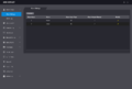
Alarm Linkage
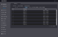
Alarm Linkage Log
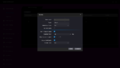
Alarm Linkage-Modify


Cable Connections
- Alarm1 = High Temp
- Alarm2 = Normal Temp or No Mask
- No alert for face detection currently.
Contact 1
| Port | Cable Color | Cable Name | Description | |
|---|---|---|---|---|
| CON1 | ||||
| Black | RD– | Negative electrode of external card reader. | ||
| Red | 35px | RD+ | Positive electrode of external card reader. | |
| Blue | File:Wire blue.svg | CASE | Tamper alarm input of the external card reader. | |
| White | 35px | D1 | Wiegand D1 input (connected to external card reader)/output (connected to controller). | |
| Green | D0 | Wiegand D0 input (connected to external card reader)/output (connected to controller). | ||
| Brown | LED | Connected to external reader indicator in | ||
| Yellow | B | RS-485 negative electrode input (connected to external card reader)/output (connected to controller, or connected to door control security module).
| ||
| Purple | A | RS-485 positive electrode input (connected to external card reader)/output (connected to controller, or connected to door control security module).
| ||
Contact 2
| Port | Cable Color | Cable Name | Description | |
|---|---|---|---|---|
| CON2 | ||||
| White and red | 35px | ALARM1_NO | Alarm 1 normally open output port | |
| White and orange | 35px | ALARM1_COM | Alarm 1 common output port. | |
| White and blue | 35px | ALARM2_NO | Alarm 2 normally open output port. | |
| White and gray | 35px | ALARM2_COM | Alarm 2 common output port. | |
| White and green | 35px | GND | Connected to the common GND port. | |
| White Brown | 35px | ALARM1 | Alarm 1 input port. | |
| White and yellow | 35px | GND | Connected to the common GND port. | |
| White and purple | ALARM2 | Alarm 2 input port. | ||
Contact 3
| Port | Cable Color | Cable Name | Description | |
|---|---|---|---|---|
| CON3 | ||||
| Black and blue | 35px | GND | Connected to the common GND port. | |
| Black and gray | 35px | SR1 | Used for door contact detection. | |
| Black and green | 35px | PUSH1 | Door open button of door No.1 | |
| Black and brown | 35px | DOOR1_COM | Lock control common port. | |
| Black and yellow | 35px | DOOR1_NO | Lock control normally open port. | |
| Black and purple | DOOR1_NC | Lock control normally closed port. | ||
Alarm Outputs 1 and 2 - New Firmware
| PLEASE NOTE: These instructions are for Alarm Outputs 1 and 2 on firmware version 1.000.10BE001.0.R.200722 and later |
|---|
High Body Temperature Indication Light

| Port | Cable Color | Cable Name | Description | |
|---|---|---|---|---|
| CON2 | ||||
| White and red | 35px | ALARM1_NO | Alarm 1 normally open output port | |
| White and orange | 35px | ALARM1_COM | Alarm 1 common output port. | |
Normal Body Temperature or No Mask Indication Light
| PLEASE NOTE: On firmware version 1.000.10BE001.0.R.200722 and later, you must set the Alarm Output 2 mode setting to either "Normal Temperature Alarm" for being triggered when a normal temperature is detected or "No Mask Alarm" for being triggered when no mask is detected |
|---|
 |

| Port | Cable Color | Cable Name | Description | |
|---|---|---|---|---|
| CON2 | ||||
| White and blue | 35px | ALARM2_NO | Alarm 2 normally open output port. | |
| White and gray | 35px | ALARM2_COM | Alarm 2 common output port. | |
Alarm Outputs 1 and 2 - Old Firmware
| PLEASE NOTE: These instructions are for Alarm Outputs 1 and 2 on firmware older than version 1.000.10BE001.0.R.200722 |
|---|
High Body Temperature Indication Light

| Port | Cable Color | Cable Name | Description | |
|---|---|---|---|---|
| CON2 | ||||
| White and blue | 35px | ALARM2_NO | Alarm 2 normally open output port. | |
| White and gray | 35px | ALARM2_COM | Alarm 2 common output port. | |
Normal Body Temperature Indication Light

| Port | Cable Color | Cable Name | Description | |
|---|---|---|---|---|
| CON2 | ||||
| White and red | 35px | ALARM1_NO | Alarm 1 normally open output port | |
| White and orange | 35px | ALARM1_COM | Alarm 1 common output port. | |
Door Strike Physical Setup

| Port | Cable Color | Cable Name | Description | |
|---|---|---|---|---|
| CON3 | ||||
| Black and brown | 35px | DOOR1_COM | Lock control common port. | |
| Black and purple | DOOR1_NC | Lock control normally closed port. | ||
Door Release Button Physical Setup

| Port | Cable Color | Cable Name | Description | |
|---|---|---|---|---|
| CON3 | ||||
| Black and blue | 35px | GND | Connected to the common GND port. | |
| Black and green | 35px | PUSH1 | Door open button of door No.1 | |
Card Reader:RS485
| Port | Cable Color | Cable Name | Description | |
|---|---|---|---|---|
| CON1 | ||||
| Yellow | B | RS-485 negative electrode input (connected to external card reader)/output (connected to controller, or connected to door control security module).
| ||
| Purple | A | RS-485 positive electrode input (connected to external card reader)/output (connected to controller, or connected to door control security module).
| ||
Door Config in DSS Express

Card Reader:Wiegand
| Port | Cable Color | Cable Name | Description | |
|---|---|---|---|---|
| CON1 | ||||
| White | 35px | D1 | Wiegand D1 input (connected to external card reader)/output (connected to controller). | |
| Green | D0 | Wiegand D0 input (connected to external card reader)/output (connected to controller). | ||
WebUI Alarm Setup
SystemUI Set Temperature Threshold
Notes
- Access Link Enable is only used when a door is configured for access for normal temperature. If the Kiosk is only used for LED lights, this option shouldn't be enabled.