Difference between revisions of "Video Intercom/VTO with SPSSLite"
(Created page with "Test") |
|||
| (One intermediate revision by the same user not shown) | |||
| Line 1: | Line 1: | ||
| − | + | =How to set up video intercom through SmartPSS Lite= | |
| + | ==Description== | ||
| + | |||
| + | This article will go over setting up a video intercom through SmartPSS Lite. | ||
| + | |||
| + | |||
| + | ==Pre-requisites== | ||
| + | * VTO | ||
| + | * VTH (You can do this without this if you want to answer the call through SmartPSS Lite) | ||
| + | * [https://dahuawiki.com/images/Files/Software/SmartPSS_Lite/General_SmartPSSLite_Eng_Win64-Install_IS_V1.004.19FU000.0.R.221101.zip SmartPSS Lite] | ||
| + | |||
| + | ==Video Instructions== | ||
| + | |||
| + | |||
| + | ==Step by Step Instructions== | ||
| + | |||
| + | '''Very important, you can only manage this setup with 1 computer via SmartPSS Lite. If you add the setup to a second computer, it will break the first setup. However, you are still able to add the VTO to DMSS to answer the call if you wish.''' | ||
| + | |||
| + | 1. First step is to initialize the devices. If you are doing a VTH and a VTO, you will have to initialize them individually since they have different password requirements. | ||
| + | |||
| + | [[File:SPSSLiteVTO1.jpg|750px]] | ||
| + | |||
| + | [[File:SPSSLiteVTO2.jpg|750px]] | ||
| + | |||
| + | 2. After initializing them, we don’t need to preconfigure them. Just add them into SmartPSS Lite. | ||
| + | |||
| + | Go to device section. | ||
| + | |||
| + | [[File:SPSSLiteVTO3.png|750px]] | ||
| + | |||
| + | Click on Autosearch and find the device in the list and click add. You will then need to input the login credentials. | ||
| + | |||
| + | [[File:SPSSLiteVTO4.png|750px]] | ||
| + | |||
| + | Both devices should now show online if the username and password were correct. | ||
| + | |||
| + | [[File:SPSSLiteVTO5.png|750px]] | ||
| + | |||
| + | 3. Once the devices are added, go to the home page of SmartPSS Lite and go to “Intercom Config” | ||
| + | |||
| + | [[File:SPSSLiteVTO6.png|750px]] | ||
| + | |||
| + | 4. Once in intercom config, click the + Add in the top left. You can then click the drop down in device name and choose the VTO. For the screenshot, I hadn’t given my devices names yet but in this case the VTO is the IP ending in 109. | ||
| + | |||
| + | [[File:SPSSLiteVTO7.png|750px]] | ||
| + | |||
| + | 5. In this next screenshot, you want to make sure that the SIP Server IP is the same IP Address as the computer IP. If the IP Address is different, it is possible you have a service running on the computer that is creating another connection. This will cause it to not function. | ||
| + | |||
| + | [[File:SPSSLiteVTO8.png|750px]] | ||
| + | |||
| + | 6. Once you have confirmed the IP for the server is correct. Click on the modify organization at the bottom. One that opens up, you want to click the plus to first create a building. In this scenario we are creating a single building and single unit. (The unit only impacts if you are involving VTH as the VTH and VTO both have to be in the same building and same unit to talk. You do require to create both.). Since I am only doing a single VTO and VTH, I created building 01 and unit 01. | ||
| + | |||
| + | Click on Modify Organization | ||
| + | |||
| + | [[File:SPSSLiteVTO9.png|750px]] | ||
| + | |||
| + | Click the plus to bring up the screen to add a building. | ||
| + | |||
| + | [[File:SPSSLiteVTO10.png|750px]] | ||
| + | |||
| + | If you are setting up a single VTO/VTH you just use 1. If you are doing multiple buildings, you can click on default area again, click the plus and then put in a 2 and you will have 01Building and 02Building | ||
| + | |||
| + | [[File:SPSSLiteVTO11.png|750px]] | ||
| + | |||
| + | Now click on the building you created in the previous step, and click the plus again to add a unit. | ||
| + | |||
| + | [[File:SPSSLiteVTO12.png|750px]] | ||
| + | |||
| + | Same thing as before, we are creating our first unit, so you want to start with a 1. | ||
| + | |||
| + | [[File:SPSSLiteVTO13.png|750px]] | ||
| + | |||
| + | Now you have a completed "Organization" which is made up of a building and a unit. Click ok to finalize. | ||
| + | |||
| + | [[File:SPSSLiteVTO14.png|750px]] | ||
| + | |||
| + | 7. Now that you have your organization setup, click on the “Select Organization” option and select 01 unit and click ok. Now you need to fill in the “extension” to the right, this is just a unique number if you are adding multiple VTOs to one setup. In this case I am only adding 1 VTO so I added 01. Once that is filled in click add at the bottom. | ||
| + | |||
| + | [[File:SPSSLiteVTO15.png|750px]] | ||
| + | |||
| + | Fill in the extension box with a 1, then click add at the bottom. | ||
| + | |||
| + | [[File:SPSSLiteVTO16.png|750px]] | ||
| + | |||
| + | 8. If everything worked out the VTO will add and the most important part is that SIP status says registered. | ||
| + | |||
| + | [[File:SPSSLiteVTO17.png|750px]] | ||
| + | |||
| + | 9. '''(ONLY DO THIS STEP IF DOING A VTO STANDALONE. SKIP TO STEP 11 IF ADDING A VTH)''' If you only have a VTO and no VTH, you can now log into the VTO and make a setting change so that the VTO will call SmartPSS lite and you can answer the call and unlock doors direct in SmartPSS Lite. Log into the VTO through a browser using the IP Address. Once in the VTO GUI, go to local settings, then put a check in the box for the call center section. By default it is set for 24 hours which is what you want since there is no VTH. After checking the box make sure to save at the bottom. | ||
| + | |||
| + | [[File:SPSSLitestandalone.png|750px]] | ||
| + | |||
| + | 10. Now that the VTO is set up. You can now test by clicking the doorbell on the VTO. When the doorbell is rung, in SmartPSS Lite you will get a green phone popup on the right like in the picture below. If you click on that, it will bring up the video and in the bottom left there is the button to unlock the door. You are done if you are using the VTO and SmartPSS Lite standalone. | ||
| + | |||
| + | [[File:SPSSLitestandalone2.png|750px]] | ||
| + | |||
| + | [[File:SPSSLitestandalone3.png|750px]] | ||
| + | |||
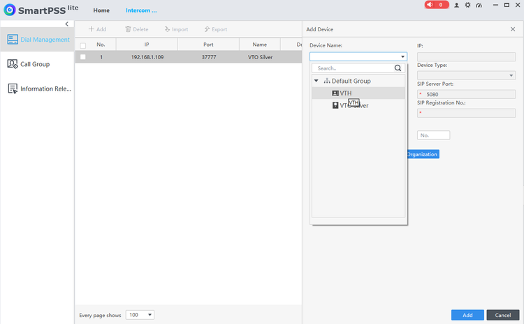
| + | 11. Now its time to add the VTH into the loop. The steps are similar to adding the VTO. Go back to the “Intercom config” then click add. This time from the device name drop down you will pick the VTH. In this case I have renamed them to make it easier. | ||
| + | |||
| + | [[File:SPSSLiteVTH1.png|750px]] | ||
| + | |||
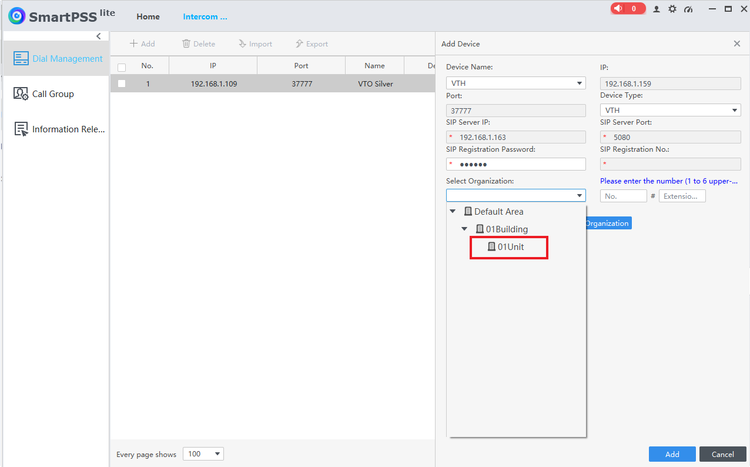
| + | 12. Once you select the VTH from the drop down. You can go down to “Select Organization” and choose the same unit as we picked for the VTO so that they exist in the same building/unit. | ||
| + | |||
| + | [[File:SPSSLiteVTH2.png|750px]] | ||
| + | |||
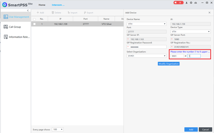
| + | 13. You will notice after choosing the unit, you now have 2 boxes to the right instead of 1 like on the VTO. For this the first box is the “calling number” that the VTO will reach the VTH at. By default, the VTO call number is 9901. You can make it whatever you want, but if you make it 1 as an example, you need to log into the VTO and change the calling number which I will include a picture of where to change that. But if this is 1 VTO and 1 VTH, it is easier to just put 9901 in the first box and you don’t need to change anything. The 2nd box is the “extension”. If you have multiple VTH being called from 1 VTO, you just need to make sure to give them unique numbers. In this case it is 1 VTH, so I gave it extension 1. If you add a 2nd, then you would just make it 2. | ||
| + | |||
| + | [[File:SPSSLiteVTH3.png|750px]] | ||
| + | |||
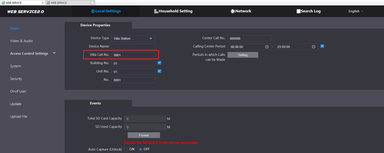
| + | If you want to change the call number, you can log into the VTO via the IP address, go to local settings and change the number there. If you put a 1 in this spot, you have to put a 1 in the first box in the above screenshot. | ||
| + | |||
| + | [[File:SPSSLiteVTH4.png|750px]] | ||
| + | |||
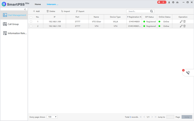
| + | 14. After you complete the above steps. Click add and now you will have the VTO and VTH added into SmartPSS Lite. You can now click the VTO doorbell and it should call through to the VTH. | ||
| + | |||
| + | [[File:SPSSLiteVTH5.png|750px]] | ||
Latest revision as of 19:27, 16 February 2023
Contents
How to set up video intercom through SmartPSS Lite
Description
This article will go over setting up a video intercom through SmartPSS Lite.
Pre-requisites
- VTO
- VTH (You can do this without this if you want to answer the call through SmartPSS Lite)
- SmartPSS Lite
Video Instructions
Step by Step Instructions
Very important, you can only manage this setup with 1 computer via SmartPSS Lite. If you add the setup to a second computer, it will break the first setup. However, you are still able to add the VTO to DMSS to answer the call if you wish.
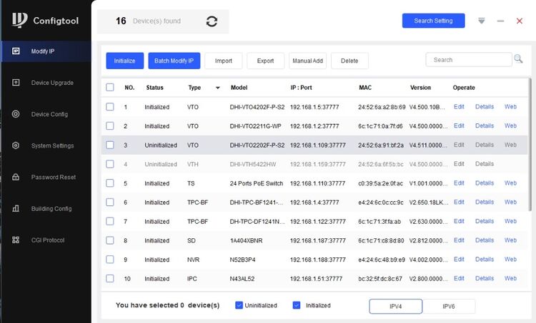
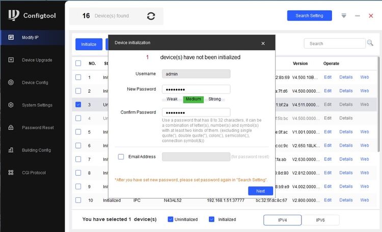
1. First step is to initialize the devices. If you are doing a VTH and a VTO, you will have to initialize them individually since they have different password requirements.
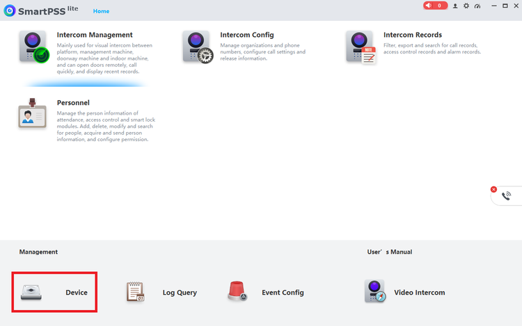
2. After initializing them, we don’t need to preconfigure them. Just add them into SmartPSS Lite.
Go to device section.
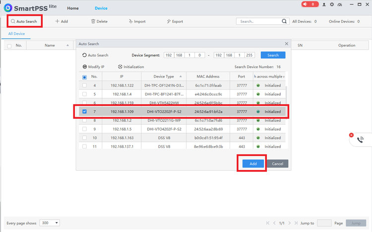
Click on Autosearch and find the device in the list and click add. You will then need to input the login credentials.
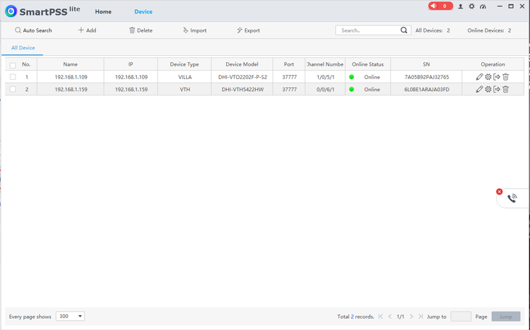
Both devices should now show online if the username and password were correct.
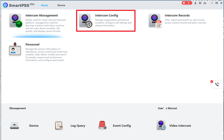
3. Once the devices are added, go to the home page of SmartPSS Lite and go to “Intercom Config”
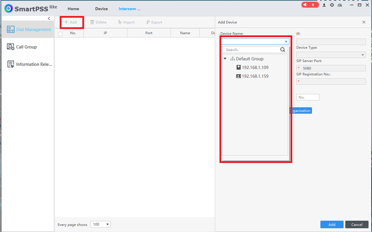
4. Once in intercom config, click the + Add in the top left. You can then click the drop down in device name and choose the VTO. For the screenshot, I hadn’t given my devices names yet but in this case the VTO is the IP ending in 109.
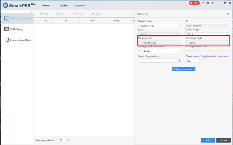
5. In this next screenshot, you want to make sure that the SIP Server IP is the same IP Address as the computer IP. If the IP Address is different, it is possible you have a service running on the computer that is creating another connection. This will cause it to not function.
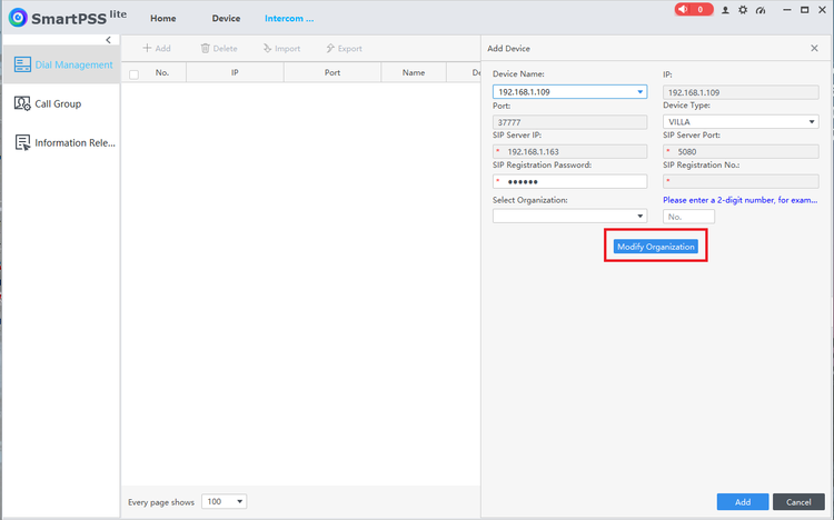
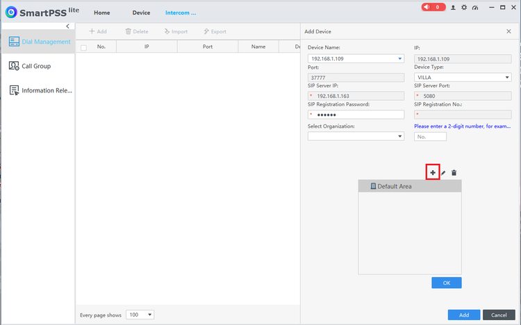
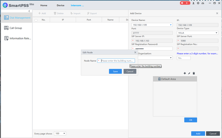
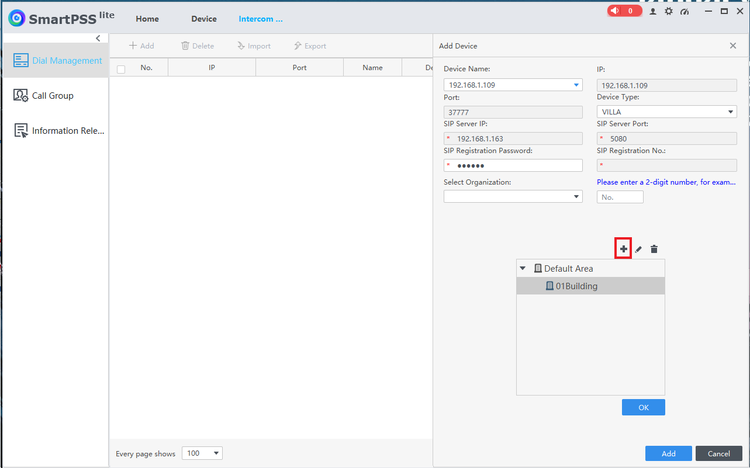
6. Once you have confirmed the IP for the server is correct. Click on the modify organization at the bottom. One that opens up, you want to click the plus to first create a building. In this scenario we are creating a single building and single unit. (The unit only impacts if you are involving VTH as the VTH and VTO both have to be in the same building and same unit to talk. You do require to create both.). Since I am only doing a single VTO and VTH, I created building 01 and unit 01.
Click on Modify Organization
Click the plus to bring up the screen to add a building.
If you are setting up a single VTO/VTH you just use 1. If you are doing multiple buildings, you can click on default area again, click the plus and then put in a 2 and you will have 01Building and 02Building
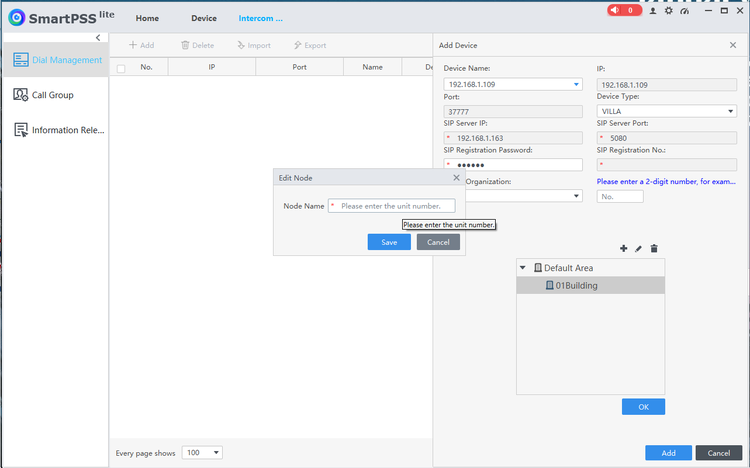
Now click on the building you created in the previous step, and click the plus again to add a unit.
Same thing as before, we are creating our first unit, so you want to start with a 1.
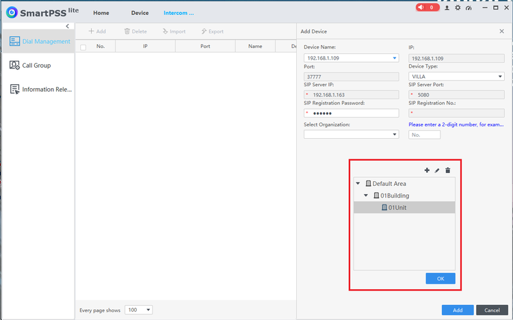
Now you have a completed "Organization" which is made up of a building and a unit. Click ok to finalize.
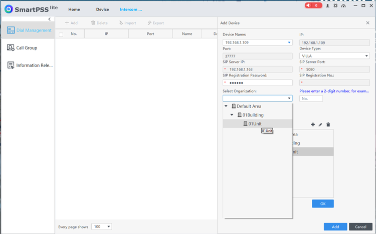
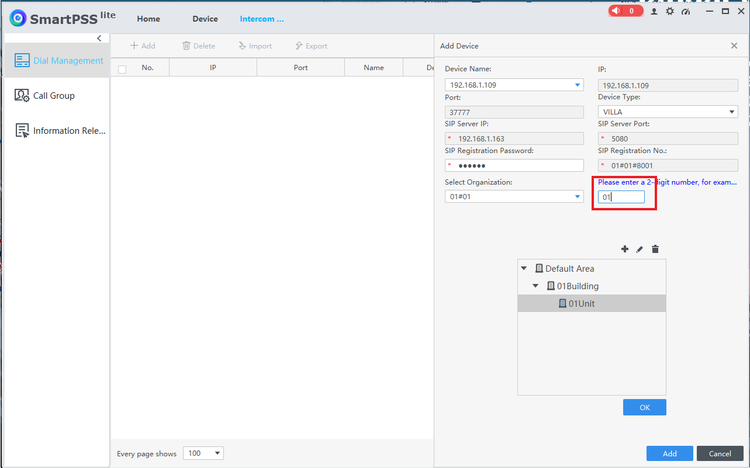
7. Now that you have your organization setup, click on the “Select Organization” option and select 01 unit and click ok. Now you need to fill in the “extension” to the right, this is just a unique number if you are adding multiple VTOs to one setup. In this case I am only adding 1 VTO so I added 01. Once that is filled in click add at the bottom.
Fill in the extension box with a 1, then click add at the bottom.
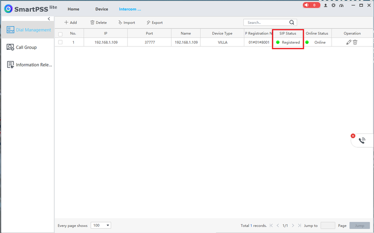
8. If everything worked out the VTO will add and the most important part is that SIP status says registered.
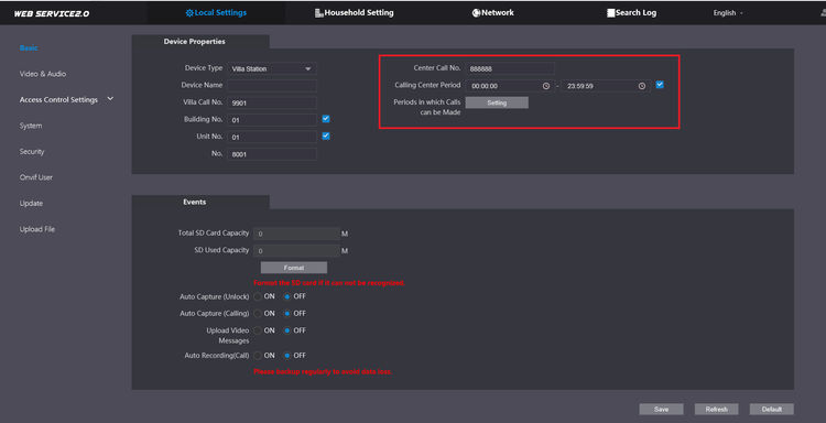
9. (ONLY DO THIS STEP IF DOING A VTO STANDALONE. SKIP TO STEP 11 IF ADDING A VTH) If you only have a VTO and no VTH, you can now log into the VTO and make a setting change so that the VTO will call SmartPSS lite and you can answer the call and unlock doors direct in SmartPSS Lite. Log into the VTO through a browser using the IP Address. Once in the VTO GUI, go to local settings, then put a check in the box for the call center section. By default it is set for 24 hours which is what you want since there is no VTH. After checking the box make sure to save at the bottom.
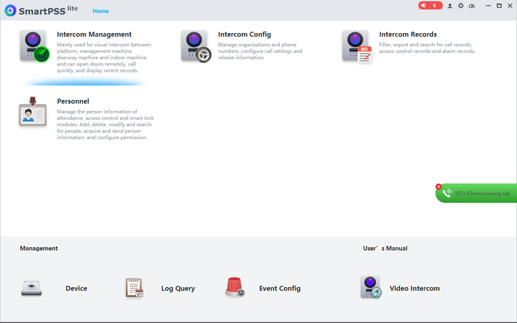
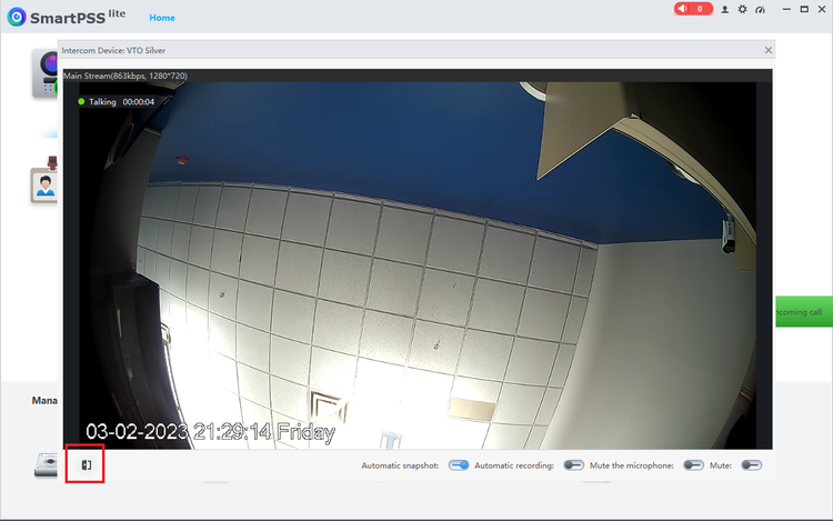
10. Now that the VTO is set up. You can now test by clicking the doorbell on the VTO. When the doorbell is rung, in SmartPSS Lite you will get a green phone popup on the right like in the picture below. If you click on that, it will bring up the video and in the bottom left there is the button to unlock the door. You are done if you are using the VTO and SmartPSS Lite standalone.
11. Now its time to add the VTH into the loop. The steps are similar to adding the VTO. Go back to the “Intercom config” then click add. This time from the device name drop down you will pick the VTH. In this case I have renamed them to make it easier.
12. Once you select the VTH from the drop down. You can go down to “Select Organization” and choose the same unit as we picked for the VTO so that they exist in the same building/unit.
13. You will notice after choosing the unit, you now have 2 boxes to the right instead of 1 like on the VTO. For this the first box is the “calling number” that the VTO will reach the VTH at. By default, the VTO call number is 9901. You can make it whatever you want, but if you make it 1 as an example, you need to log into the VTO and change the calling number which I will include a picture of where to change that. But if this is 1 VTO and 1 VTH, it is easier to just put 9901 in the first box and you don’t need to change anything. The 2nd box is the “extension”. If you have multiple VTH being called from 1 VTO, you just need to make sure to give them unique numbers. In this case it is 1 VTH, so I gave it extension 1. If you add a 2nd, then you would just make it 2.
If you want to change the call number, you can log into the VTO via the IP address, go to local settings and change the number there. If you put a 1 in this spot, you have to put a 1 in the first box in the above screenshot.
14. After you complete the above steps. Click add and now you will have the VTO and VTH added into SmartPSS Lite. You can now click the VTO doorbell and it should call through to the VTH.
