Difference between revisions of "Access Control/How To Setup DHI ASI1212A"
(Created page with "==How to Setup DHI-ASI1212A==") |
|||
| Line 1: | Line 1: | ||
==How to Setup DHI-ASI1212A== | ==How to Setup DHI-ASI1212A== | ||
| + | |||
| + | ===Prerequisites=== | ||
| + | |||
| + | * The DHI-ASI1201A-D unit and included hardware | ||
| + | * Drill or screw driver | ||
| + | * Wires for alarm and light | ||
| + | * DC power supply for device | ||
| + | * router or drill bit for wires | ||
| + | |||
| + | ===Installation=== | ||
| + | |||
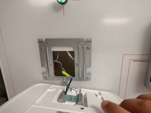
| + | 1. Drill out a hole where the wiring will enter the wall, and mount the supplied bracket with the rounded tab pointing downwards. | ||
| + | |||
| + | [[File:ASI1201Asetup021.jpg|500x500px]] | ||
| + | |||
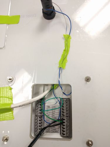
| + | 2. Connect the wiring according to what inputs and outputs you are configuring, here we will wire a simple LED that is powered off of the 12v supply. The unlock relay here is wired supplying power through the 12v terminal to the NC or NO terminal and then through the COM to the LED then back to ground where the circuit will terminate. | ||
| + | |||
| + | [[File:ASI1201Asetup001.jpg|500x500px]] | ||
| + | |||
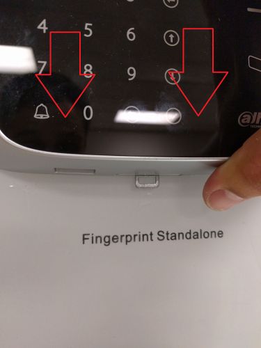
| + | 3. Now slide the access controller downwards onto the bracket until the rounded tab locks into place. If you need to remove the terminal use a flat head screw driver to push the plastic tab on the controller to unlock it and then slide up. | ||
| + | |||
| + | [[File:ASI1201Asetup022.jpg|500x500px]] | ||
| + | |||
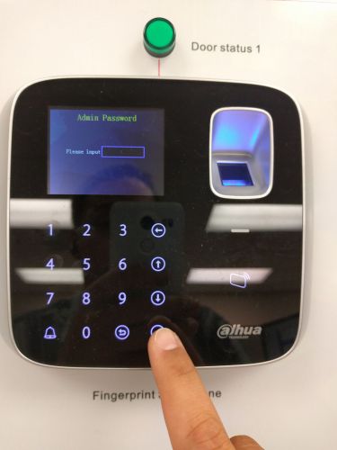
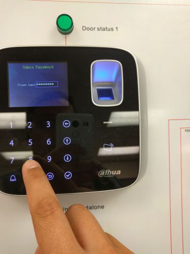
| + | 4. After you have powered your ASI1201A press the check button on the lower right corner of the number pad to log into the administrator account. The default password is 88888888, then press the check button again. | ||
| + | |||
| + | [[File:ASI1201Asetup007.jpg|500x500px]][[File:ASI1201Asetup008.jpg|500x500px]] | ||
| + | |||
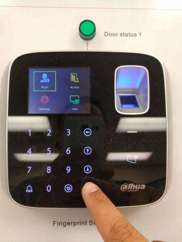
| + | 5. Now Select "Right" to setup an account. | ||
| + | |||
| + | [[File:ASI1201Asetup009.jpg|500x500px]] | ||
| + | |||
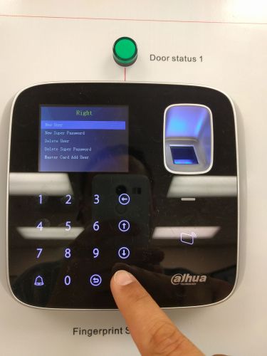
| + | 6. Select "New User". | ||
| + | |||
| + | [[File:ASI1201Asetup010.jpg|500x500px]] | ||
| + | |||
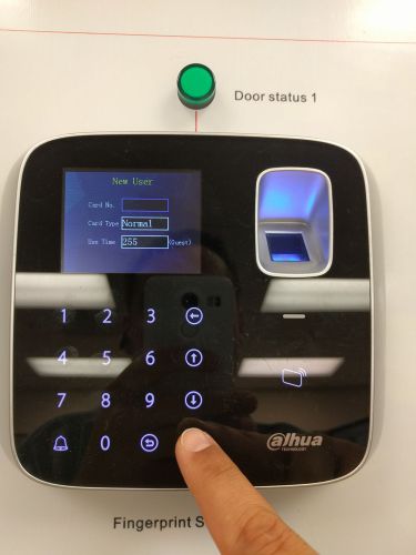
| + | 7. You will be asked for a card number, you can either scan the card for automatic input, or enter the letters and numbers manually. To enter letters you must press and hold they corresponding key (1-a, 2-b, 3-c, 4-d, 5-e, 6-f). Alternatively a NFC scanning tool or phone application such as NFC tools can get the serial number of the card remotely. Once entered press the check button. | ||
| + | |||
| + | [[File:ASI1201Asetup011.jpg|500x500px]] | ||
| + | [[File:ASI1201Asetup012.jpg|500x500px]] | ||
| + | [[File:ASI1201Asetup024.png|500x500px]] | ||
| + | |||
| + | 8. Now enter a password for the account, and enter a validity date, in this case I used the default maximum date so the access rights do not expire. | ||
| + | |||
| + | [[File:ASI1201Asetup013.jpg|500x500px]] | ||
| + | |||
| + | 9. Now we will set up a finger print profile, this is optional but it is recommended. | ||
| + | |||
| + | [[File:ASI1201Asetup014.jpg|500x500px]] | ||
| + | |||
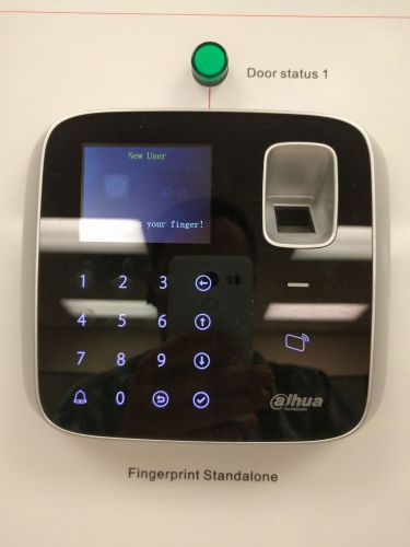
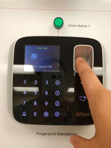
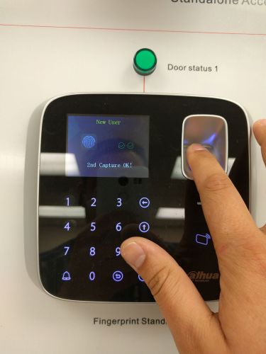
| + | 10. When prompted please put the clients finger on the reader. Then when prompted for a second read please use the same finger again. | ||
| + | |||
| + | [[File:ASI1201Asetup015.jpg|500x500px]] | ||
| + | [[File:ASI1201Asetup016.jpg|500x500px]] | ||
| + | [[File:ASI1201Asetup017.jpg|500x500px]] | ||
| + | |||
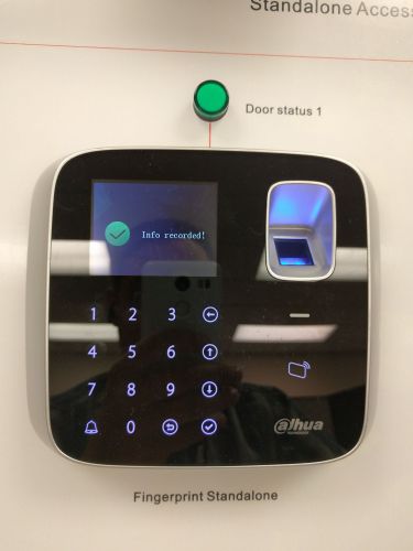
| + | 11. Make sure you see the confirmation screen that the information has been recorded. | ||
| + | |||
| + | [[File:ASI1201Asetup018.jpg|500x500px]] | ||
| + | |||
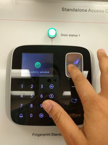
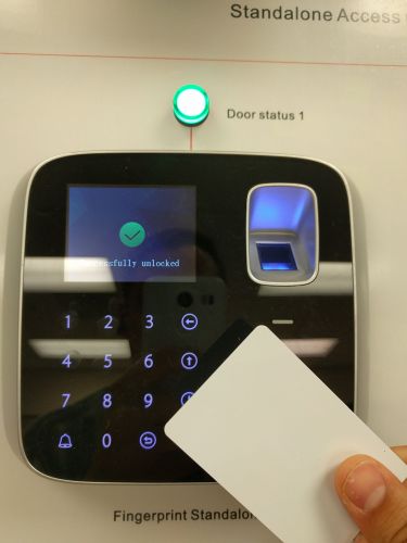
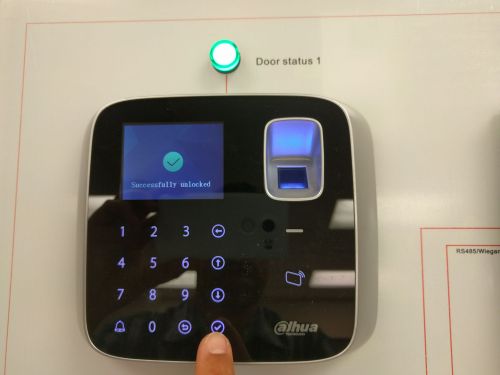
| + | 12. Now test any of these methods: Finger print, Card, or Password to confirm they are working correctly. | ||
| + | |||
| + | [[File:ASI1201Asetup019.jpg|500x500px]] | ||
| + | [[File:ASI1201Asetup020.jpg|500x500px]] | ||
| + | [[File:ASI1201Asetup003.jpg|500x500px]] | ||
Revision as of 17:11, 15 June 2016
How to Setup DHI-ASI1212A
Prerequisites
- The DHI-ASI1201A-D unit and included hardware
- Drill or screw driver
- Wires for alarm and light
- DC power supply for device
- router or drill bit for wires
Installation
1. Drill out a hole where the wiring will enter the wall, and mount the supplied bracket with the rounded tab pointing downwards.
2. Connect the wiring according to what inputs and outputs you are configuring, here we will wire a simple LED that is powered off of the 12v supply. The unlock relay here is wired supplying power through the 12v terminal to the NC or NO terminal and then through the COM to the LED then back to ground where the circuit will terminate.
3. Now slide the access controller downwards onto the bracket until the rounded tab locks into place. If you need to remove the terminal use a flat head screw driver to push the plastic tab on the controller to unlock it and then slide up.
4. After you have powered your ASI1201A press the check button on the lower right corner of the number pad to log into the administrator account. The default password is 88888888, then press the check button again.
5. Now Select "Right" to setup an account.
6. Select "New User".
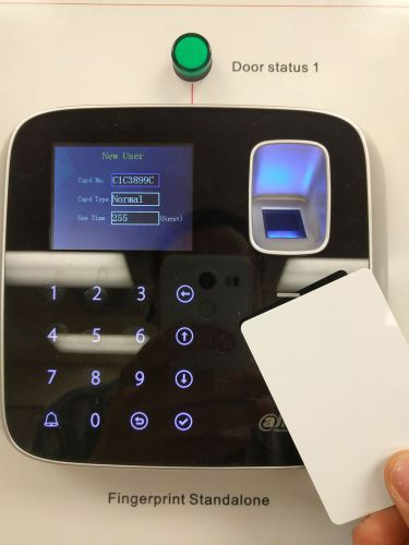
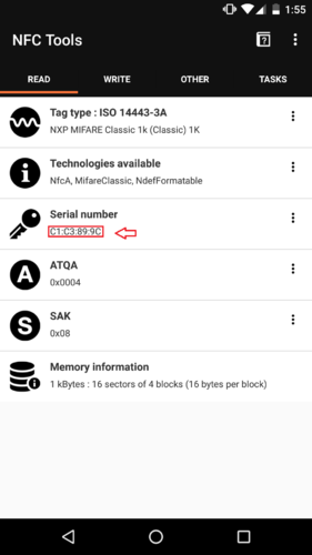
7. You will be asked for a card number, you can either scan the card for automatic input, or enter the letters and numbers manually. To enter letters you must press and hold they corresponding key (1-a, 2-b, 3-c, 4-d, 5-e, 6-f). Alternatively a NFC scanning tool or phone application such as NFC tools can get the serial number of the card remotely. Once entered press the check button.
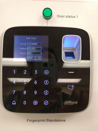
8. Now enter a password for the account, and enter a validity date, in this case I used the default maximum date so the access rights do not expire.
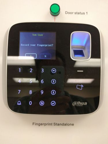
9. Now we will set up a finger print profile, this is optional but it is recommended.
10. When prompted please put the clients finger on the reader. Then when prompted for a second read please use the same finger again.
11. Make sure you see the confirmation screen that the information has been recorded.
12. Now test any of these methods: Finger print, Card, or Password to confirm they are working correctly.
