Difference between revisions of "NVRiSettingNetwork"
(→WIFI) |
(→WIFI) |
||
| Line 53: | Line 53: | ||
[[file:NVRiSettingNetworkWIFI.png]] | [[file:NVRiSettingNetworkWIFI.png]] | ||
| − | '''Note''' | + | '''Note: '''This function is for some series product only. |
| − | |||
| − | + | The WIFI AP interface is shown as below. Here you can set WIFI hotspot, so that the network camera can use the hotspot to connect to the network. | |
| − | The WIFI AP interface is shown as below | ||
* SSID: It is to set SSID name. You can use this name to search the device. | * SSID: It is to set SSID name. You can use this name to search the device. | ||
Revision as of 00:20, 3 November 2015
Contents
NVR Interface-Setting-Network
TCP/IP
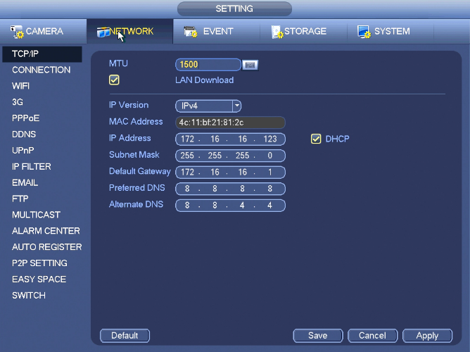
The single network adapter interface is shown as in Figure 4‑99 and the dual network adapters interface is shown as in Figure 4‑100.
- Network Mode : Includes multiple access, fault tolerance, and load balancing
- Multiple-address mode: eth0 and eth1 operate separately. You can use the services such as HTTP, RTP service via etho0 or the eth1. Usually you need to set one default card (default setup is etho) to request the auto network service form the device-end such as DHCP, email, FTP and etc. In multiple-address mode, system network status is shown as offline once one card is offline.
- Network fault-tolerance: In this mode, device uses bond0 to communicate with the external devices. You can focus on one host IP address. At the same time, you need to set one master card. Usually there is only one running card (master card).System can enable alternate card when the master card is malfunction. The system is shown as offline once these two cards are both offline. Please note these two cards shall be in the same LAN.
- Load balance: In this mode, device uses bond0 to communicate with the external device. The eth0 and eth1 are both working now and bearing the network load. Their network load are general the same. The system is shown as offline once these two cards are both offline. Please note these two cards shall be in the same LAN.
- Default Network Card: Please select eth0/eth1/bond0(optional) after enable multiple-access function
- Main Network Card: Please select eth0/eth1 (optional).after enable multiple access function.
Note: The dual-Ethernet port series support the above three configurations and supports functions as multiple-access, fault-tolerance and load balancing.
- IP Version: There are two options: IPv4 and IPv6. Right now, system supports these two IP address format and you can access via them.
- MAC address: The host in the LAN can get a unique MAC address. It is for you to access in the LAN. It is read-only.
- IP address: Here you can use up/down button (pq) or input the corresponding number to input IP address. Then you can set the corresponding subnet mask the default gateway.
- Default gateway: Here you can input the default gateway. Please note system needs to check the validity of all IPv6 addresses. The IP address and the default gateway shall be in the same IP section. That is to say, the specified length of the subnet prefix shall have the same string.
- DHCP: It is to auto search IP. When enable DHCP function, you can not modify IP/Subnet mask /Gateway. These values are from DHCP function. If you have not enabled DHCP function, IP/Subnet mask/Gateway display as zero. You need to disable DHCP function to view current IP information. Besides, when PPPoE is operating, you can not modify IP/Subnet mask /Gateway.
- MTU: It is to set MTU value of the network adapter. The value ranges from 1280-7200 bytes. The default setup is 1500 bytes. Please note MTU modification may result in network adapter reboot and network becomes off. That is to say, MTU modification can affect current network service. System may pop up dialog box for you to confirm setup when you want to change MTU setup. Click OK button to confirm current reboot, or you can click Cancel button to terminate current modification. Before the modification, you can check the MTU of the gateway; the MTU of the NVR shall be the same as or is lower than the MTU of the gateway. In this way, you can reduce packets and enhance network transmission efficiency.
The following MTU value is for reference only.
- 1500: Ethernet information packet max value and it is also the default value. It is the typical setup when there is no PPPoE or VPN. It is the default setup of some router, switch or the network adapter.
- 1492: Recommend value for PPPoE.
- 1468: Recommend value for DHCP.
- Preferred DNS server: DNS server IP address.
- Alternate DNS server: DNS server alternate address.
- Transfer mode: Here you can select the priority between fluency/video qualities.
- LAN download: System can process the downloaded data first if you enable this function. The download speed is 1.5X or 2.0X of the normal speed.
- LAN download: System can process the downloaded data first if you enable this function. The download speed is 1.5X or 2.0X of the normal speed.
After completing all the setups please click save button, system goes back to the previous menu.
Connection
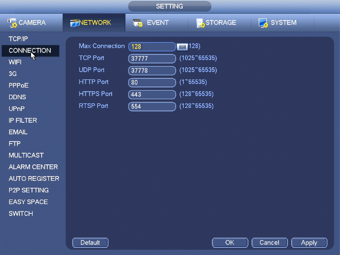
The connection setup interface is shown below:
- Max connection: system support maximal 128 users. 0 means there is no connection limit.
- TCP port: Default value is 37777.
- UDP port: Default value is 37778.
- HTTP port: Default value is 80.
- HTTPS port: Default value is 443.
- RTSP port: Default value is 554.
Important: System needs to reboot after you changed and saved any setup of the above four ports. Please make sure the port values here do not conflict.
WIFI
Note: This function is for some series product only.
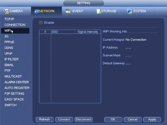
The WIFI AP interface is shown as below. Here you can set WIFI hotspot, so that the network camera can use the hotspot to connect to the network.
- SSID: It is to set SSID name. You can use this name to search the device.
- Password: It is to set SSID password. You can use this password to connect to the network.
- Authentication mode: Select authentication from the dropdown list.
- Encrypt type: Select encryption type from the dropdown list.
- Start IP/End IP: Input start IP and end IP. The NVR can allocate the IP address in the range you specified here.
- WPS: Click WPS button to enable WPS function. After the network camera enabled this function, it can automatically connect to the network.
- Remote device: In the list, you can view the network camera(s) that connected to the NVR. It includes signal intensity, IP, MAC address, bit rate, channel number, type, status and etc.
3G
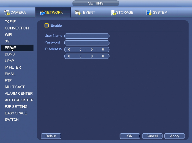
PPPoE
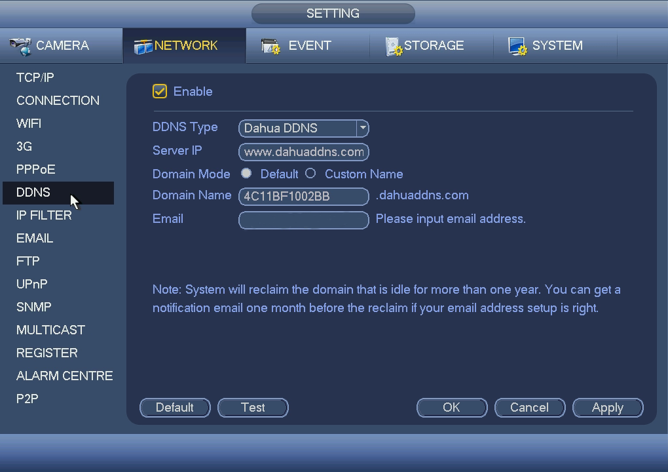
DDNS
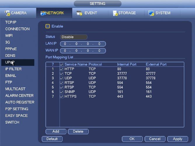
UPnP
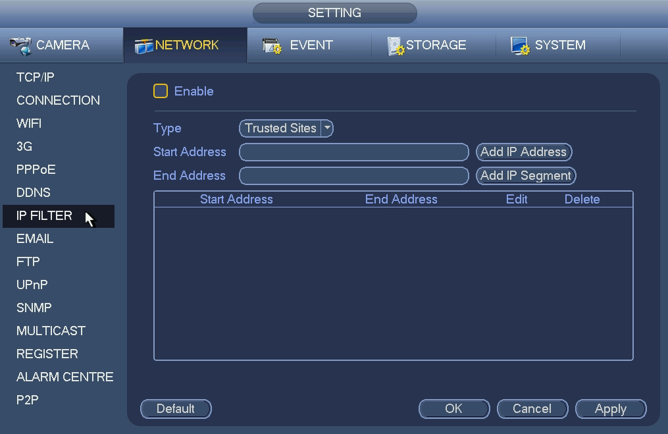
IP Filter
FTP
Multicast
Alarm Center
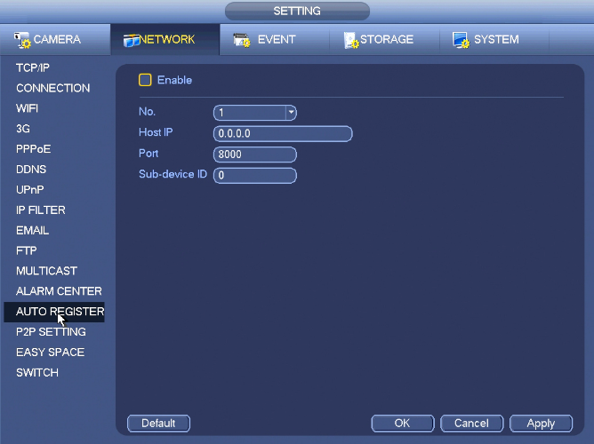
Auto Register
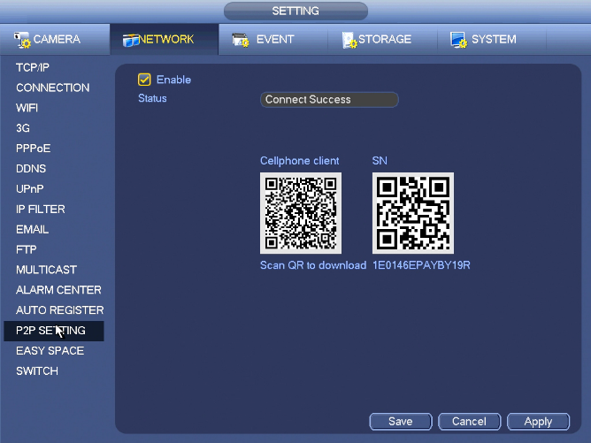
P2P Setting
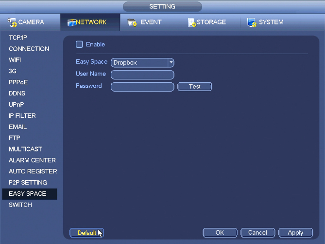
Easy Space
Switch
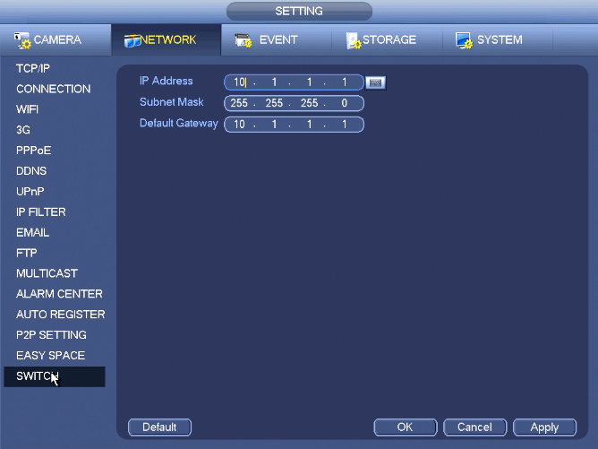 The built-in switch function is for product of PoE port.
From Main menu->Setting->Network->Switch, you can set switch IP address, subnet mask, gateway and etc.

