Difference between revisions of "Video Intercom/VideoAC Intercom DSS"
| Line 27: | Line 27: | ||
4. Click on '''Finish''' once you see the green check marks. | 4. Click on '''Finish''' once you see the green check marks. | ||
| − | [[File: | + | [[File:Face_Controller_3a.jpg|900px]] |
| − | 5. Now we need to | + | 5. Now we need to log into the WebUI of the DHI-ASI8213SA. Go to your browser such as chrome, and then enter the IP Address and you will get to a login page like below. Login with the Admin and the password you created during the initialization. |
| − | [[File: | + | [[File:Face_Controller_4.jpg|900px]] |
| − | 6. | + | 6. Next we want to go to the Intercom section. |
| − | [[File: | + | [[File:Face_Controller_5.jpg|900px]] |
| − | 7. | + | 7. Once in the intercom section, you want to be on the "Basic" section. From here click the device type drop down, and choose the VTO option. |
| − | |||
| − | |||
| − | + | [[File:Face_Controller_6.jpg|900px]] | |
| − | [[File: | + | 8. Next what we want to do is put a check in the boxes to the right of the Building No. and the Unit No. Now that you have checks in those boxes you can provide a building number and Unit Number. Since we only have 1 device, it doesn't really matter what you put here |
| + | |||
| + | [[File:Face_Controller_7.jpg|900px]] | ||
9. Now that the VDP devices are initialized we need to get them on the local network. Start by going to '''Search Settings''' and enter the password of the VTOs. This will allow us to make changes to the VTOs using Configtool. Click on '''OK''' to proceed. | 9. Now that the VDP devices are initialized we need to get them on the local network. Start by going to '''Search Settings''' and enter the password of the VTOs. This will allow us to make changes to the VTOs using Configtool. Click on '''OK''' to proceed. | ||
Revision as of 17:43, 3 April 2024
Contents
Description
This article will go over the setup of our Video Access Controller to be used as an Intercom in Combination with DSS Pro v8.4 and the DSS Agile VDP App
DSS Pro V8 will be acting as our SIP Server. The Intercom devices will need to point to the system user on DSS Pro V8.
system user is mainly used for server maintenance. For live monitoring you will want to create a new user with Muilt-client Login disabled.
Prerequisites
- Latest Configtool
- DSS Pro V8
- DHI-ASI8213SA-W
Step by Step Instructions
Initializing the Video Intercom Devices
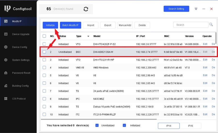
1. Open Configtool and initialize the Video Access Controller first. Add a checkmark to all the Video Access Controllers on your network and click on Initialize. (In this case we just have the one)
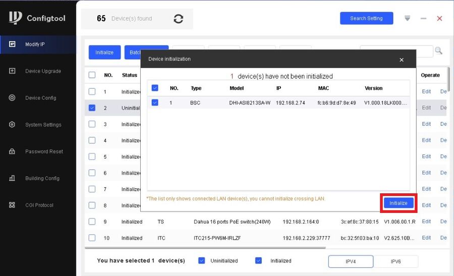
2. Click on Initialize again
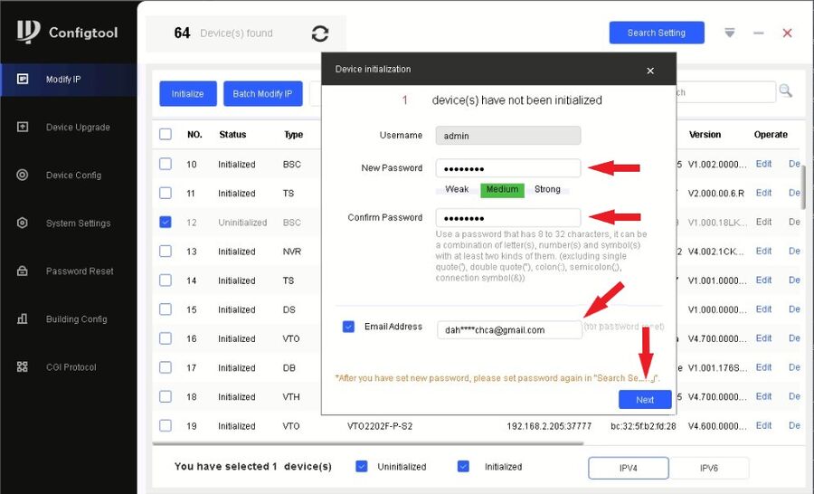
3. Enter the password and confirm it. Do NOT forget to enter an email. Entering an email will help you reset the password when needed. Click on Next to proceed.
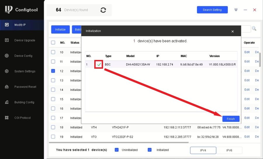
4. Click on Finish once you see the green check marks.
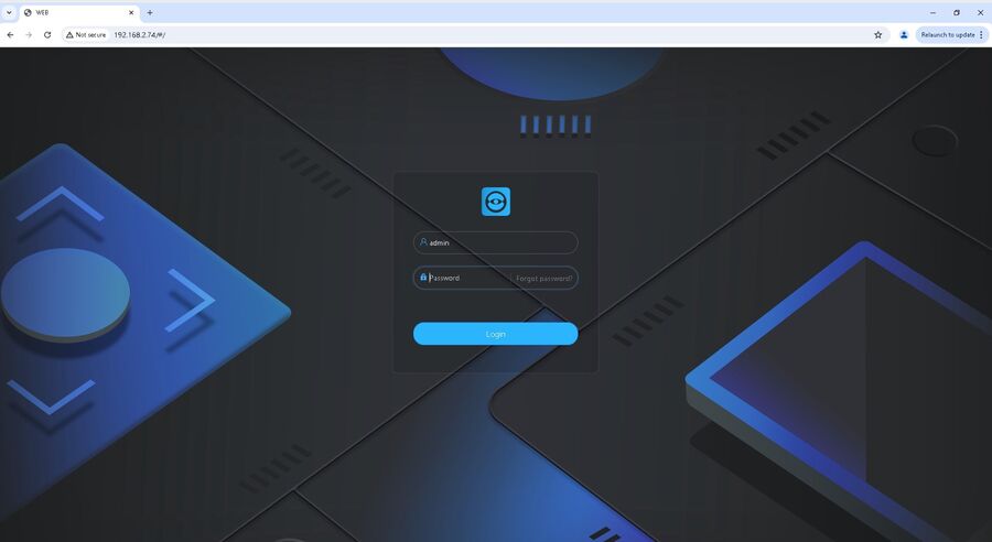
5. Now we need to log into the WebUI of the DHI-ASI8213SA. Go to your browser such as chrome, and then enter the IP Address and you will get to a login page like below. Login with the Admin and the password you created during the initialization.
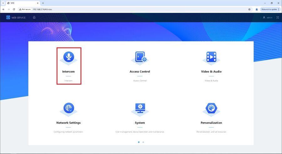
6. Next we want to go to the Intercom section.
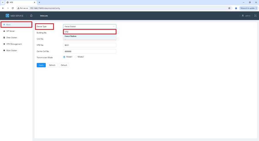
7. Once in the intercom section, you want to be on the "Basic" section. From here click the device type drop down, and choose the VTO option.
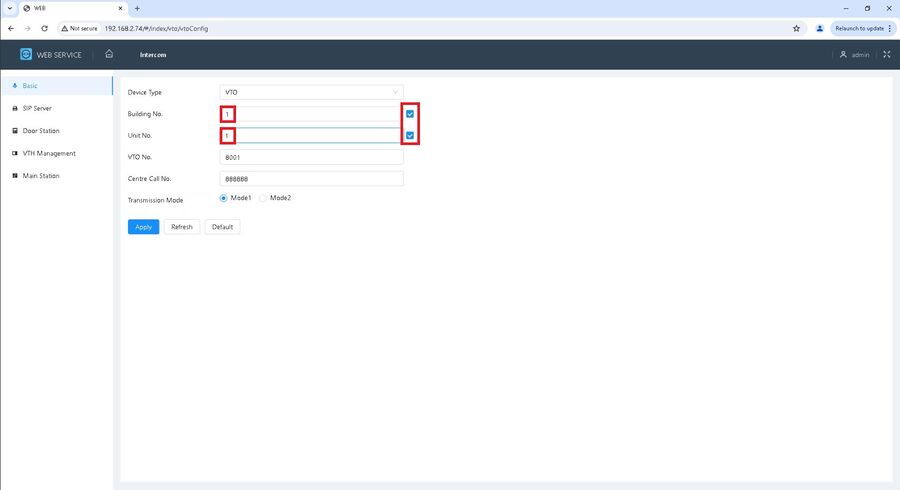
8. Next what we want to do is put a check in the boxes to the right of the Building No. and the Unit No. Now that you have checks in those boxes you can provide a building number and Unit Number. Since we only have 1 device, it doesn't really matter what you put here
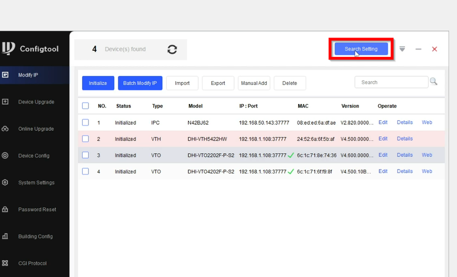
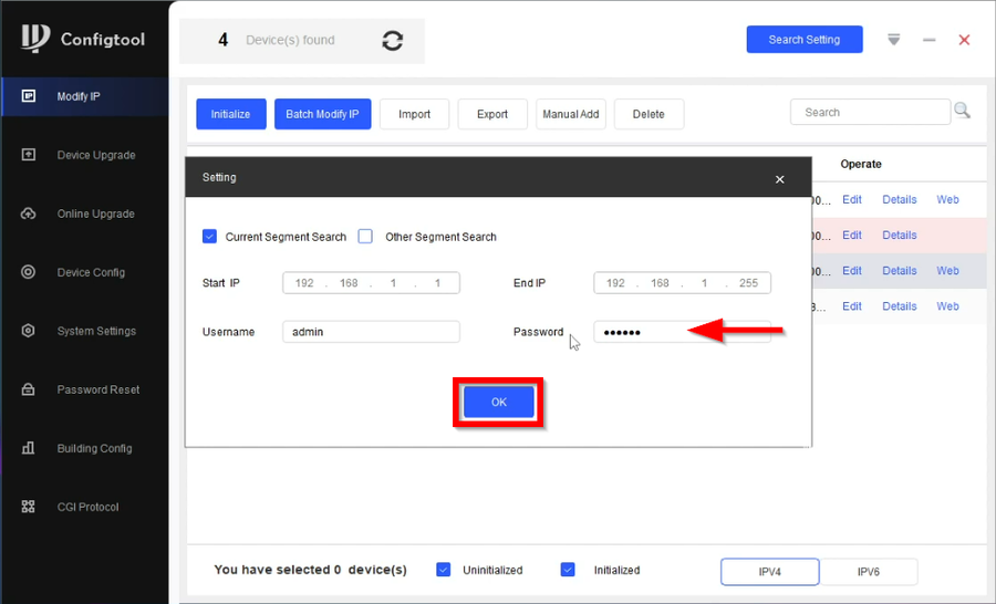
9. Now that the VDP devices are initialized we need to get them on the local network. Start by going to Search Settings and enter the password of the VTOs. This will allow us to make changes to the VTOs using Configtool. Click on OK to proceed.
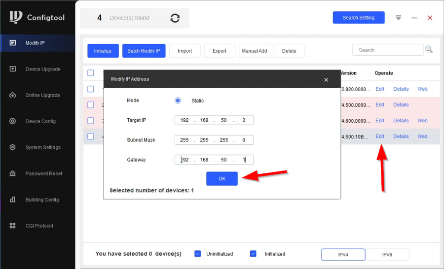
10. Click on Edit to modify the VTOs IP. Enter an available IP on your local network and hit OK to save. Do this same step to the remaining VTOs.
11. Next are the VTHs. Lets go back to Search Settings
12. Enter the 6-digit password for the VTHs and click on OK
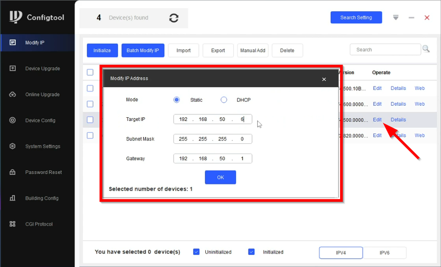
13. Now click on Edit on all the VTHs to change their IP addresses.
Your VTOs and VTHs are now Initialized and on the local network.
Building Config
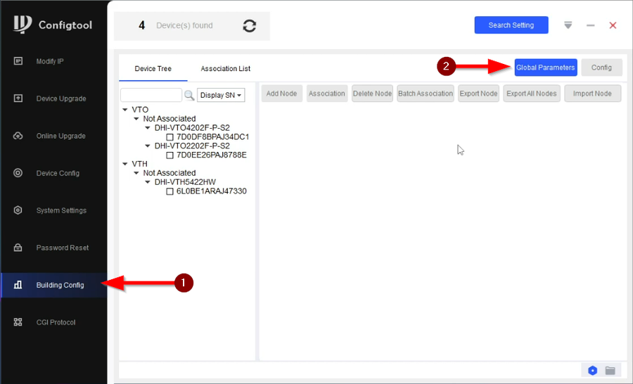
14. Now that the devices are initialized go to Building Config and click on Global Parameters.
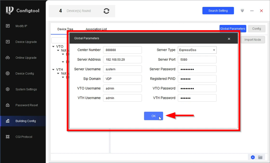
15. We now need to enter the required information.
Entering the correct information to global parameters will ensure that the Video Intercom devices will be configured properly. The SIP information will be sent to all VDP devices to ensure they all speak to the SIP Server. The Login Information for VTO and VTH will ensure that Configtool has permission to login and assign it the SIP information. Here is a chart that will help you enter the correct info.
| Global Parameter | |
|---|---|
| Center Number = Leave Default | Server Type = Express/DSS |
| Sever Address = IP Address for the DSS Server | Server Port = 5080 |
| Sever Username = system | Sever Password = Enter password for system |
| Sip Domain = VDP | Register PWD = Leave Default |
| VTO Username = Enter VTO username | VTO Password = Enter VTO password |
| VTH Username = Enter VTH username | VTH Password = Enter VTH Password |
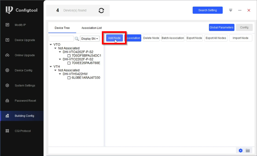
16. We can now start our project by clicking on Add Node
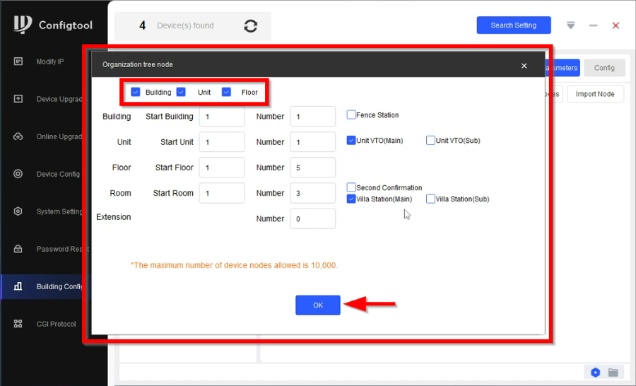
17. Enter the correct information in order to create a project tree that's appropriate for your setup. Below is a chart explaining the options.
| Organization tree node | ||
|---|---|---|
| Building | Start Building = The starting number of the building | Number = The amount of buildings for the project |
| Unit | Start Unit = The starting unit number of the unit | Number = The max amount of units per building |
| Floor | Start Floor = The starting number of the floor
|
Number = The max amount of floors per unit |
| Room | Start Room = The starting number of the rooms
|
Number = The max amount of rooms per floor |
| Extension | Number = The max amount of extensions per room
| |
Check the Unit VTO(Main) if you have a single apartment style VTOs. Also check Unit VTO(Sub) if you have multiple apartment VTOs.
Check Villa Station(Main) if you have a single villa style VTO. Also check Villa Station(Sub) if you have multiple villa VTOs.
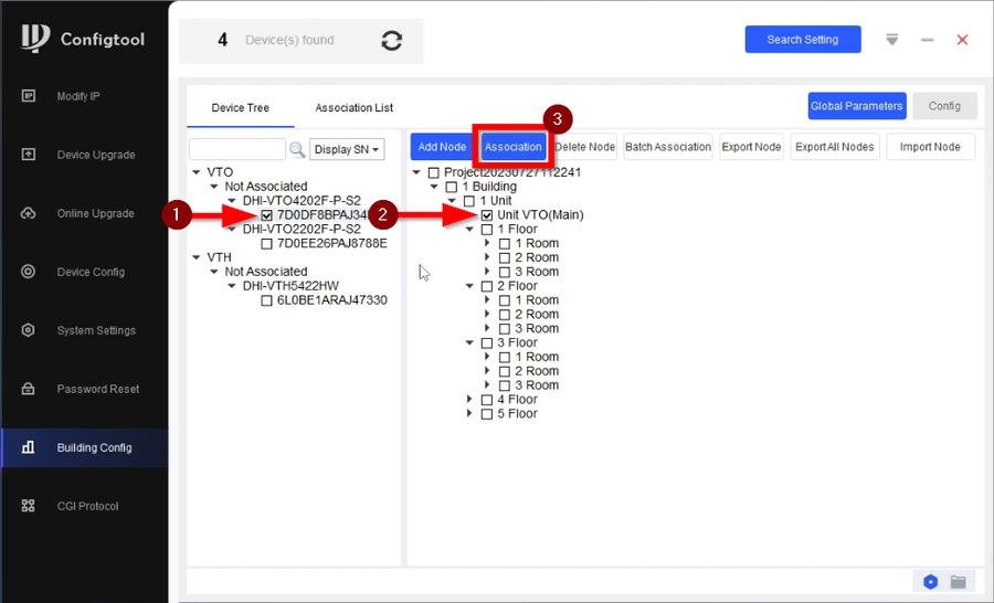
18. Once you create your node you will need to associate the devices to their corresponding entry. It's advised to have some sort of spreadsheet to document IP addresses/ SN of the devices to easily locate them from the list on the left. One by one you will check the device and the entry on the node then click on Association.
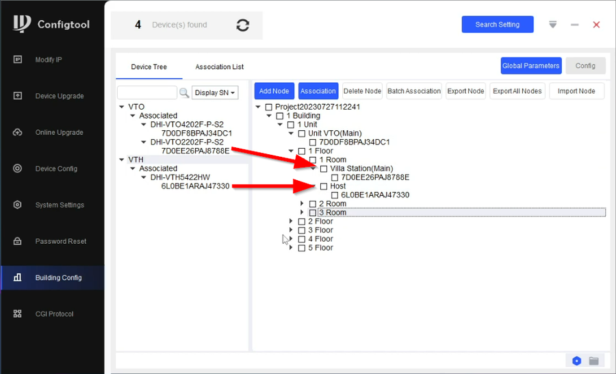
19. You will now see the device under the node entry. Do the same to all the devices
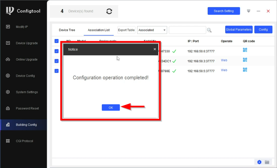
20. Once all the devices are associated to their entry, go to Association List tab. Check all the devices and click on Config
21. Click on OK once Confitool is done configuring the devices.
Adding Devices to DSS Pro
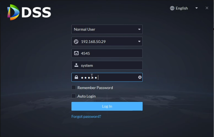
22. Open and login to DSS Client.
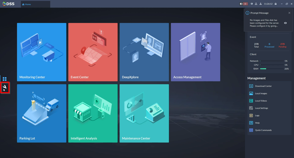
23. Go to the Configuration tab that looks like a wrench icon
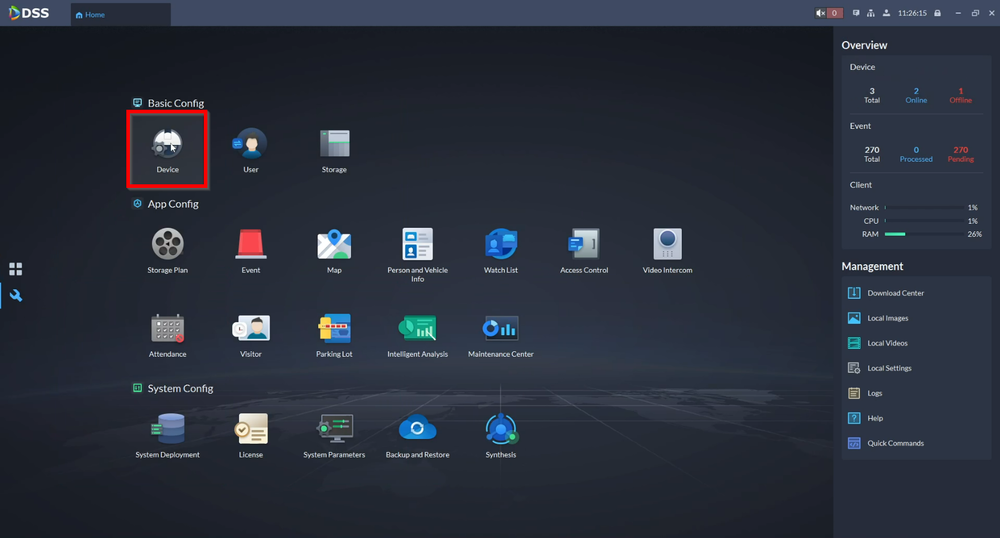
24. Click on Device
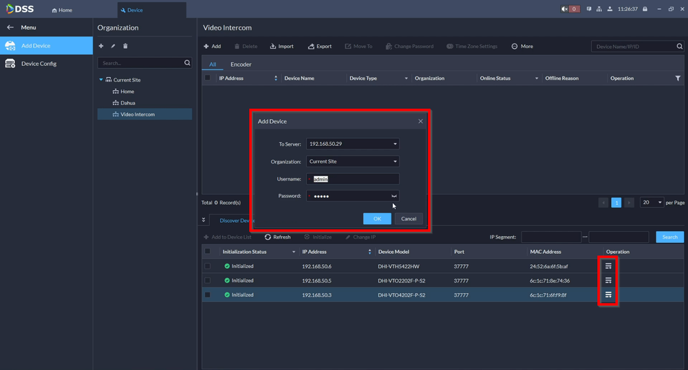
25. From here add the devices by either manually entering the IP address of the devices or by doing a search.
26. You should now see the online status on all your devices.
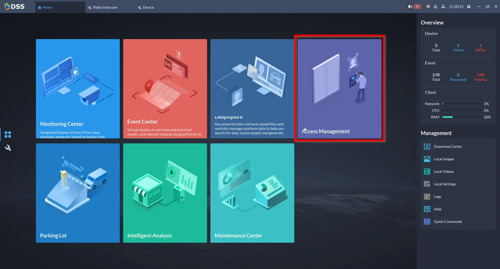
27. Go to Access management
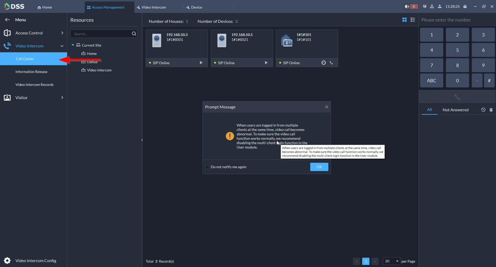
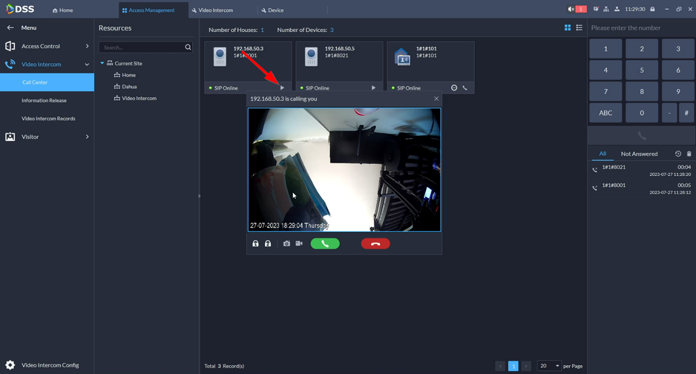
28. Navigate to Video Intercom -> Call Center and from here you can see the SIP status of your devices and initiate a two-way talk to each. If you are still logged in to the system account you will get a Multi-client error message. This means the account you are using has the multi-client Login option enabled. Its recommended to turn it off for full functionality.
29. Create a new user and make sure that Multi-client Login is disabled.
30. You can now receive calls by either tapping on the Center Management icon on an apartment style VTO keypad or dialing "888888"
