Difference between revisions of "Software/JVSG CCTV Design Software"
(→Step by Step Instructions) |
|||
| Line 35: | Line 35: | ||
| + | [[File:JVSGCCTV006.jpg|500x500px]] | ||
| − | |||
| + | [[File:JVSGCCTV007.jpg|500x500px]] | ||
| + | 2. Once opened select a camera manufacturer. | ||
| − | + | [[File:JVSGCCTV008.jpg|500x500px]] | |
| + | 3. Select The Model of camera. | ||
| − | + | [[File:JVSGCCTV009.jpg|500x500px]] | |
| + | 4. Select the installation height the camera will be mounted at in this simulation. | ||
| + | [[File:JVSGCCTV010.jpg|500x500px]] | ||
| − | 5. | + | 5. Select Focal Length of the camera. |
| + | [[File:JVSGCCTV011.jpg|500x500px]] | ||
| + | 6. Select the Viewing Angles, or the tilt angle of the camera. | ||
| − | + | [[File:JVSGCCTV013.jpg|500x500px]] | |
| + | 7. Select Site Plan to get an overhead view of the map, and to modify the position of the camera. If you selected a PTZ this also gives a good indication of it's view range. | ||
| + | [[File:JVSGCCTV014.jpg|500x500px]] | ||
| − | + | 8. The icons under the Site Plan tab represent view orientation, model, and wall placement. These are the tools provided to simulate people, objects, and viewing areas. | |
| + | [[File:JVSGCCTV016.jpg|500x500px]] | ||
| + | 9. Once you have placed your objects in the simulation you can now see them in all view modes, two dimensional and three dimensional. | ||
| − | + | [[File:JVSGCCTV018.jpg|500x500px]] | |
| + | 10. Select 3D Views to view the camera(s) setup in a 3D rendering. | ||
| + | [[File:JVSGCCTV019.jpg|500x500px]] | ||
| − | + | 11. Select DVR View to simulate a 2x2, 3x3, and 4x4 demo view on each camera that has been setup. | |
| + | [[File:JVSGCCTV020.jpg|500x500px]] | ||
| + | 12. Select the Network Bandwith & Disk Space tab to calculate the rates on your cameras. | ||
| − | + | [[File:JVSGCCTV021.jpg|500x500px]] | |
Revision as of 17:52, 19 July 2016
Contents
How to Use JVSG: CCTV Design Software
Description
JVSG is an IP Video System Design Tool that can digitally render your ideal camera setup. This tool can help with systems integration in camera technology by demonstrating both two and three dimensional layouts that can describe the field of view given the model and position of a camera.
Setup sensor size, display ratio, and focal length to simulate cameras that are not listed among the program.
Set up and render a three dimensional scene with walls, buses, people, and other models for an immersive perspective. JSVG allows you to even import your own models into the rendering.
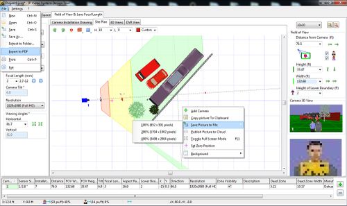
Export pdf or pictures of the renderings.
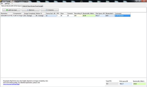
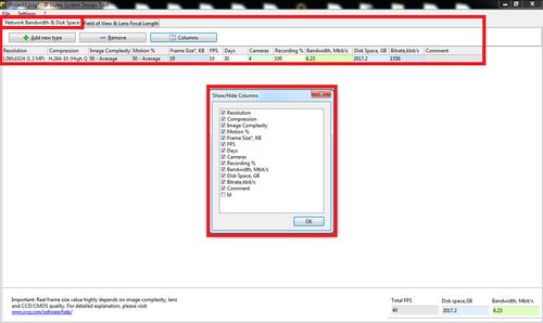
Included is also a camera calculator that gives you the ability to calculate storage space and bit rates based upon resolution, compression, image complexity, number of cameras, fps, and frame size.
Pre-Requisites
- PC with Windows 10, Windows 8, Windows 7, Vista, Windows XP SP2
- Use AMD/ATI Radeon graphics cards for large video surveillance projects
Video Instructions
Step by Step Instructions
Setting up a camera
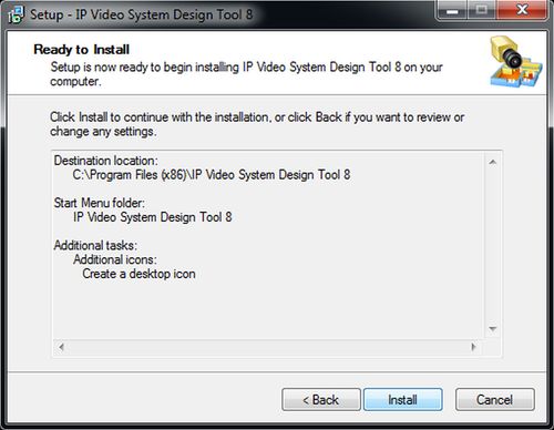
1. Download http://www.jvsg.com/software/ip-video-system-design-tool/ extract, install, and open JVSG IP Video Systems Design.
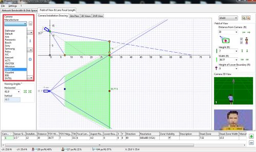
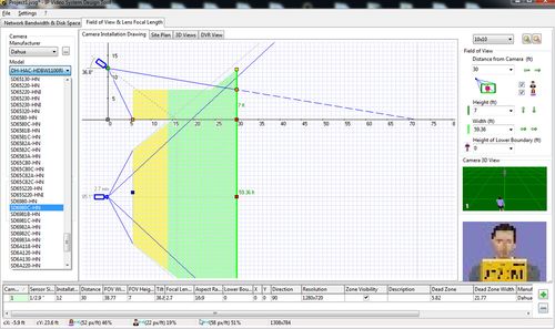
2. Once opened select a camera manufacturer.
3. Select The Model of camera.
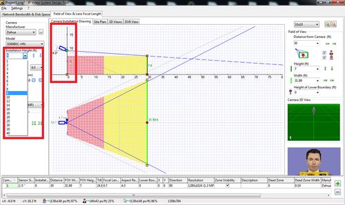
4. Select the installation height the camera will be mounted at in this simulation.
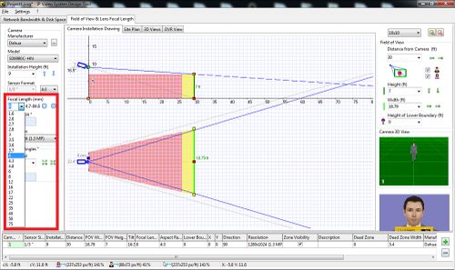
5. Select Focal Length of the camera.
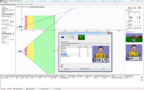
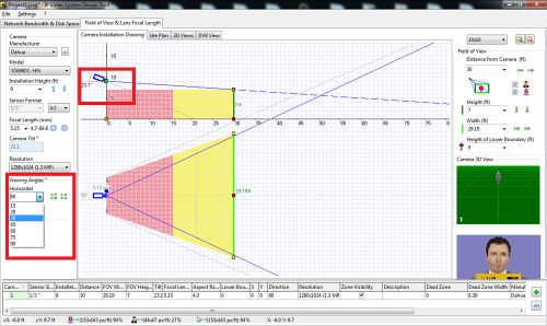
6. Select the Viewing Angles, or the tilt angle of the camera.
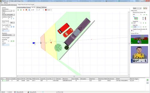
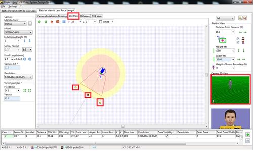
7. Select Site Plan to get an overhead view of the map, and to modify the position of the camera. If you selected a PTZ this also gives a good indication of it's view range.
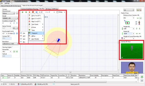
8. The icons under the Site Plan tab represent view orientation, model, and wall placement. These are the tools provided to simulate people, objects, and viewing areas.
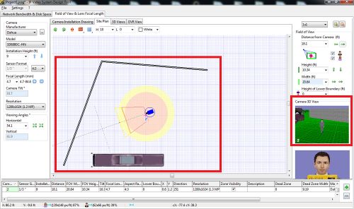
9. Once you have placed your objects in the simulation you can now see them in all view modes, two dimensional and three dimensional.
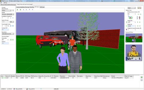
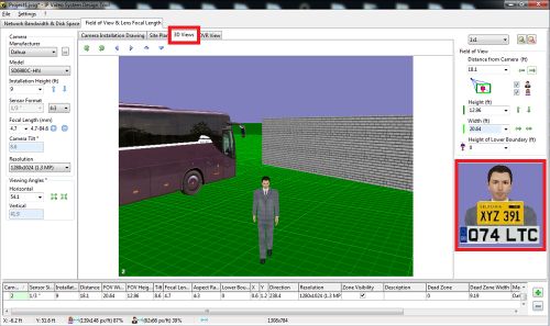
10. Select 3D Views to view the camera(s) setup in a 3D rendering.
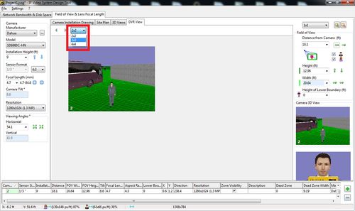
11. Select DVR View to simulate a 2x2, 3x3, and 4x4 demo view on each camera that has been setup.
12. Select the Network Bandwith & Disk Space tab to calculate the rates on your cameras.
