Difference between revisions of "NVR/Alarm Panel"
(Created page with "==Alarm COnnection== ===Alarm Port=== The alarm port is shown as below. The following figure is based on the 78 series. file:NVRAlarmDiagram1.png {| class="wikitable" wi...") |
(→Alarm COnnection) |
||
| Line 58: | Line 58: | ||
| width="379"| | | width="379"| | ||
485 communication port. They are used to control devices such as PTZ. Please parallel connect 120TΩ between A/B cables if there are too many PTZ decoders. | 485 communication port. They are used to control devices such as PTZ. Please parallel connect 120TΩ between A/B cables if there are too many PTZ decoders. | ||
| + | |||
| + | |} | ||
| + | '''Note''' | ||
| + | |||
| + | * Different models support different alarm input ports. Please refer to the specifications sheet for detailed information. | ||
| + | * Slight difference may be found on the alarm port layout. | ||
| + | |||
| + | ===Alarm input port=== | ||
| + | Connect the positive end (+) of the alarm input device to the alarm input port (ALARM IN 1~16) of the NVR. Connect the negative end (-) of the alarm input device to the ground end ([[file:PanelIconGround.png]]) of the NVR. | ||
| + | |||
| + | [[file:NVRAlarmDiagram2.png]] | ||
| + | |||
| + | '''Note''' | ||
| + | |||
| + | * There are two alarm input types: NO/NC. | ||
| + | * When connect the ground port of the alarm device to the NVR, you can use any of the GND ports (). | ||
| + | * Connect the NC port of the alarm device to the alarm input port (ALARM) of the NVR. | ||
| + | * When there is peripheral power supplying for the alarm device, please make sure it is earthed with the NVR. | ||
| + | |||
| + | |||
| + | ===Alarm relay specifications=== | ||
| + | |||
| + | {| class="wikitable" width="597" | ||
| + | |- | ||
| + | | colspan="2" width="117"| | ||
| + | '''Model: ''' | ||
| + | |||
| + | | colspan="3" width="480"| | ||
| + | '''JRC-27F''' | ||
| + | |||
| + | |- | ||
| + | | width="116"| | ||
| + | Material of the touch | ||
| + | |||
| + | | colspan="3" width="480"| | ||
| + | Silver | ||
| + | |||
| + | | width="1"| | ||
| + | |||
| + | |- | ||
| + | | rowspan="4" width="116"| | ||
| + | Rating(Resistance Load) | ||
| + | |||
| + | | colspan="2" width="216"| | ||
| + | Rated switch capacity | ||
| + | |||
| + | | width="264"| | ||
| + | 30VDC 2A, 125VAC 1A | ||
| + | |||
| + | | width="1"| | ||
| + | |||
| + | |- | ||
| + | | colspan="2" width="216"| | ||
| + | Maximum switch power | ||
| + | |||
| + | | width="264"| | ||
| + | 125VA 160W | ||
| + | |||
| + | | width="1"| | ||
| + | |||
| + | |- | ||
| + | | colspan="2" width="216"| | ||
| + | Maximum switch voltage | ||
| + | |||
| + | | width="264"| | ||
| + | 250VAC, 220VDC | ||
| + | |||
| + | | width="1"| | ||
| + | |||
| + | |- | ||
| + | | colspan="2" width="216"| | ||
| + | Maximum switch currency | ||
| + | |||
| + | | width="264"| | ||
| + | 1A | ||
| + | |||
| + | | width="1"| | ||
| + | |||
| + | |- | ||
| + | | rowspan="3" width="116"| | ||
| + | Insulation | ||
| + | |||
| + | | colspan="2" width="216"| | ||
| + | Between touches with same polarity | ||
| + | |||
| + | | width="264"| | ||
| + | 1000VAC 1minute | ||
| + | |||
| + | | width="1"| | ||
| + | |||
| + | |- | ||
| + | | colspan="2" width="216"| | ||
| + | Between touches with different polarity | ||
| + | |||
| + | | width="264"| | ||
| + | 1000VAC 1minute | ||
| + | |||
| + | | width="1"| | ||
| + | |||
| + | |- | ||
| + | | colspan="2" width="216"| | ||
| + | Between touch and winding | ||
| + | |||
| + | | width="264"| | ||
| + | 1000VAC 1minute | ||
| + | |||
| + | | width="1"| | ||
| + | |||
| + | |- | ||
| + | | width="116"| | ||
| + | Surge voltage | ||
| + | |||
| + | | colspan="2" width="216"| | ||
| + | Between touches with same polarity | ||
| + | |||
| + | | width="264"| | ||
| + | 1500V (10×160us) | ||
| + | |||
| + | | width="1"| | ||
| + | |||
| + | |- | ||
| + | | width="116"| | ||
| + | Length of open time | ||
| + | |||
| + | | colspan="3" width="480"| | ||
| + | 3ms max | ||
| + | |||
| + | | width="1"| | ||
| + | |||
| + | |- | ||
| + | | width="116"| | ||
| + | Length of close time | ||
| + | |||
| + | | colspan="3" width="480"| | ||
| + | 3ms max | ||
| + | |||
| + | | width="1"| | ||
| + | |||
| + | |- | ||
| + | | rowspan="2" width="116"| | ||
| + | Longevity | ||
| + | |||
| + | | colspan="2" width="216"| | ||
| + | Mechanical | ||
| + | |||
| + | | width="264"| | ||
| + | 50×106 MIN (3Hz) | ||
| + | |||
| + | | width="1"| | ||
| + | |||
| + | |- | ||
| + | | colspan="2" width="216"| | ||
| + | Electrical | ||
| + | |||
| + | | width="264"| | ||
| + | 200×103 MIN (0.5Hz) | ||
| + | |||
| + | | width="1"| | ||
| + | |||
| + | |- | ||
| + | | width="116"| | ||
| + | Temperature | ||
| + | |||
| + | | colspan="3" width="480"| | ||
| + | -40℃ ~+70℃ | ||
| + | |||
| + | | width="1"| | ||
|} | |} | ||
Revision as of 19:43, 26 October 2015
Alarm COnnection
Alarm Port
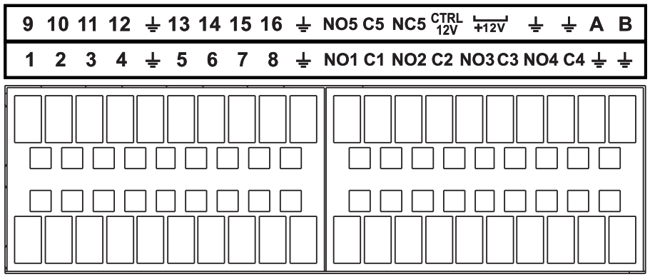
The alarm port is shown as below. The following figure is based on the 78 series.
|
Icon |
Function |
|
1~16 |
ALARM1~ALARM16. The alarm becomes activated in the low level. |
|
NO1 C1,NO2 C2,NO3 C3,NO4 C4 |
Four NO activation output groups. (On-off button). |
|
NO5 C5 NC5 |
One NO/NC activation output group. (On-off button). |
|
CTRL 12V |
Control power output. Disable power output when alarm is canceled. Current is 500mA. |
|
+12V |
Rated current output. Current is 500mA. |
|
GND | |
|
A/B |
485 communication port. They are used to control devices such as PTZ. Please parallel connect 120TΩ between A/B cables if there are too many PTZ decoders. |
Note
- Different models support different alarm input ports. Please refer to the specifications sheet for detailed information.
- Slight difference may be found on the alarm port layout.
Alarm input port
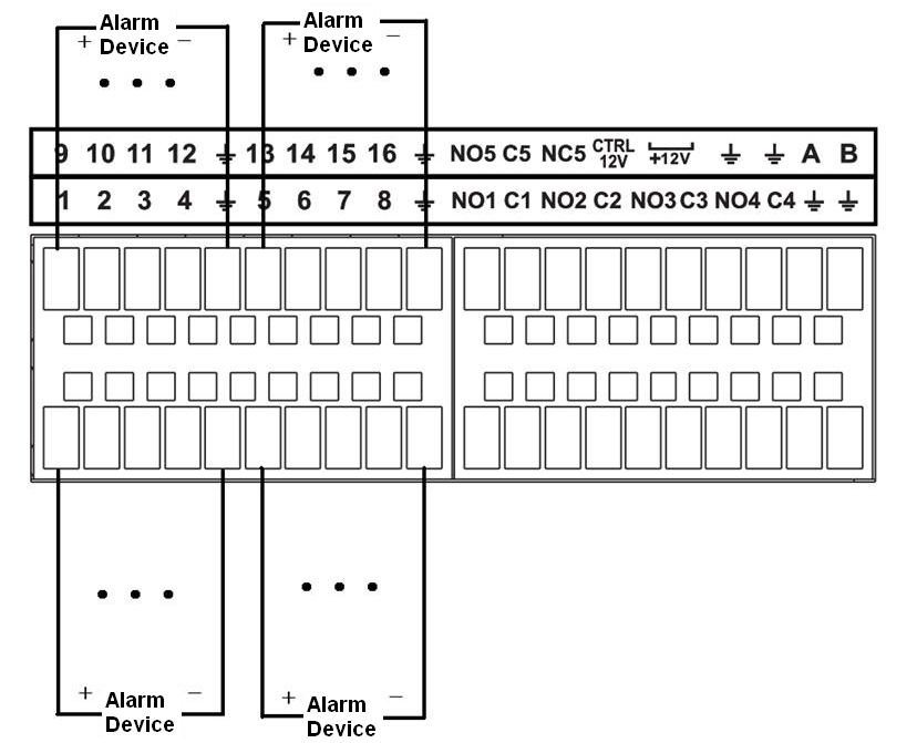
Connect the positive end (+) of the alarm input device to the alarm input port (ALARM IN 1~16) of the NVR. Connect the negative end (-) of the alarm input device to the ground end (![]() ) of the NVR.
) of the NVR.
Note
- There are two alarm input types: NO/NC.
- When connect the ground port of the alarm device to the NVR, you can use any of the GND ports ().
- Connect the NC port of the alarm device to the alarm input port (ALARM) of the NVR.
- When there is peripheral power supplying for the alarm device, please make sure it is earthed with the NVR.
Alarm relay specifications
|
Model: |
JRC-27F | |||
|
Material of the touch |
Silver |
|||
|
Rating(Resistance Load) |
Rated switch capacity |
30VDC 2A, 125VAC 1A |
||
|
Maximum switch power |
125VA 160W |
|||
|
Maximum switch voltage |
250VAC, 220VDC |
|||
|
Maximum switch currency |
1A |
|||
|
Insulation |
Between touches with same polarity |
1000VAC 1minute |
||
|
Between touches with different polarity |
1000VAC 1minute |
|||
|
Between touch and winding |
1000VAC 1minute |
|||
|
Surge voltage |
Between touches with same polarity |
1500V (10×160us) |
||
|
Length of open time |
3ms max |
|||
|
Length of close time |
3ms max |
|||
|
Longevity |
Mechanical |
50×106 MIN (3Hz) |
||
|
Electrical |
200×103 MIN (0.5Hz) |
|||
|
Temperature |
-40℃ ~+70℃ |
|||

