Difference between revisions of "Basic Setup/How to Terminate CAT5"
(→Diagram) |
(→Diagram) |
||
| Line 2: | Line 2: | ||
===Description=== | ===Description=== | ||
===Diagram=== | ===Diagram=== | ||
| − | |||
{| style="float:right; clear:right" | {| style="float:right; clear:right" | ||
|- | |- | ||
| Line 13: | Line 12: | ||
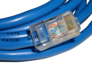
|[[File:Cat 5.jpg|thumb|Category 5 [[patch cable]] in [[T568B]] wiring]] | |[[File:Cat 5.jpg|thumb|Category 5 [[patch cable]] in [[T568B]] wiring]] | ||
|} | |} | ||
| − | |||
| − | |||
| − | |||
| − | |||
===Prerequisites=== | ===Prerequisites=== | ||
Revision as of 19:00, 6 July 2017
Contents
How to Terminate CAT5
Description
Diagram
| Template:T568A Wiring |
| Template:T568B Wiring |
Prerequisites
- Cat5 cable
- Cat5 Modular Crimper
- Cat5 Heads
Video Instructions
Step by Step Instructions
1. On your Cat5 Modular Crimper, locate the half circle. That is the cable stripper. Insert one end of the cable appprox. 3-4 inches into that half circle.
2. Remove the plastic sheeth.
3. Cut the fiber string.
4. Untwist the twisted pairs.
5. You want to arrange the cables, from left to right, as follows:
- White-Orange
- Orange
- White-Green
- Blue
- White-Blue
- Green
- White-Brown
- Brown
6. Once you have the cables arranged in the above order, cut the cables 1/2 to 1 inch from the plastic sheathing.
7. Insert the cables into the Cat5 head. Ensure each cable lines up in their correct spot.
8. Insert the Cat5 head into the Cat5 Modular Crimper, and squeeze.
9. Repeat this process for the other end of the Cat5 cable.
10. Test the cable with a Cat5 cable tester to verify that the cable was terminated properly.
