Difference between revisions of "IVS/Global Setup"
| Line 61: | Line 61: | ||
Click inside the video frame to draw a frame | Click inside the video frame to draw a frame | ||
| + | |||
| + | This frame must include all of the objects/areas being used as a reference for the rulers | ||
[[File:IVS_Global_Setup_-_4.jpg|500px]] | [[File:IVS_Global_Setup_-_4.jpg|500px]] | ||
Revision as of 22:53, 1 August 2019
Contents
Global Setup
Description
This article will show you how to set the global rules for IVS analysis.
Depth of field calibration allows the camera to determine the corresponding relationship between the 2D image captured by the camera and the actual 3D object using one horizontal ruler and three vertical rulers that are defined by the user using the corresponding actual distance.
Note: Global setup is for the Fast-Moving IVS feature
Example
Prerequisites
- Supported device with IVS feature
Metric to Imperial Conversion
- 1 Meter = 3.28 Feet
- 2 Meters = 6.56 Feet
- 3 Meters = 9.84 Feet
Example
Global Setup Best Practices
- The camera must be installed at a medium or distant view with an installation height of more than 3 meters.
- Scenes with parallel view or ceiling mounted are not supported
- Horizontal surfaces can be calibrated, not vertical walls or sloping surfaces
- Not applicable for scenes that have a distorted view such as captured by super wide-angle or a fisheye camera
Vertical rulers: Three rulers must be created. Select three reference objects with fixed height that are positioned in a triangular distribution
Horizontal ruler: Use a reference object with a known length such as a sign on the road or make an actual measurement of the ground
The scene in this guide will use the lamp posts that are in the scene since they are uniform height and positioned in a triangulated arrangement.
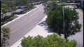
Picture of scene
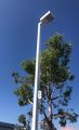
Light post used as a vertical ruler reference in this example
Completed Rulers


Video Instructions
Coming Soon
Step by Step Instructions
1. Log into the web interface of the camera

2. Click Setting

3. Click Event > IVS
Click the tab labeled 'Global Setup'

4. The calibration zone must be created
Click inside the video frame to draw a frame
This frame must include all of the objects/areas being used as a reference for the rulers

5. Left click to draw

6. The 3 vertical reference rules must be drawn.
These objects must be identical in height.
Toggle the button next to Vertical then click Add Rules
Then click inside the video frame to drag and draw the line

7. One Vertical ruler has been created in this scene

8.Repeat the same process twice to create 2 more Vertical rulers in the scene

9. The horizontal reference rule must be drawn.
Toggle the button next to Horizontal then click Add Rules
Then click inside the video frame to drag and draw the line

10. All rules complete

11. Enter the actual length of the created Rulers by first selecting the Rule in the list above then entering the value in the 'Actual Length' field (in meters)

12. Click Save once all parameters have been set

13. To test calibration accuracy:
- Use the drop-down to select from Height or Weight Verification
- Click Calibration Validation

Left click inside the Calibrate Region to draw a line

Zoomed:

Sign used as reference:

In this example the Calibration appears to be correct, the drawn line reports a value of 1.70
Sign measures 5 feet 10 inches = 1.778 meters
In the case of a major difference between the estimated value and the actual one, fine-tune or reset the parameters until the error requirement is met.