Difference between revisions of "Thermal/DHI-ASI7213X-T1/Instructions/Alarm Input and Output"
(→High Body Temperature Indication Light) |
(→Normal Body Temperature or No Mask Indication Light) |
||
| Line 212: | Line 212: | ||
|} | |} | ||
| − | [[File:Normal Temp alarm Setup.png|700px|right]] | + | [[File:Normal Temp alarm Setup-newfw.png|700px|right]] |
{| class="wikitable" | {| class="wikitable" | ||
!|Port | !|Port | ||
Revision as of 21:34, 20 October 2020
Contents
- 1 Alarm Input and Output
Alarm Input and Output


Web Interface
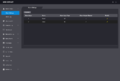
Alarm Linkage
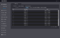
Alarm Linkage Log
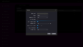
Alarm Linkage-Modify


Cable Connections
- Alarm1 = High Temp
- Alarm2 = Normal Temp or No Mask
- No alert for face detection currently.
Contact 1
| Port | Cable Color | Cable Name | Description | |
|---|---|---|---|---|
| CON1 | ||||
| Black | 35px | RD– | Negative electrode of external card reader. | |
| Red | 35px | RD+ | Positive electrode of external card reader. | |
| Blue | 35px | CASE | Tamper alarm input of the external card reader. | |
| White | 35px | D1 | Wiegand D1 input (connected to external card reader)/output (connected to controller). | |
| Green | 35px | D0 | Wiegand D0 input (connected to external card reader)/output (connected to controller). | |
| Brown | 35px | LED | Connected to external reader indicator in | |
| Yellow | 35px | B | RS-485 negative electrode input (connected to external card reader)/output (connected to controller, or connected to door control security module).
| |
| Purple | A | RS-485 positive electrode input (connected to external card reader)/output (connected to controller, or connected to door control security module).
| ||
Contact 2
| Port | Cable Color | Cable Name | Description | |
|---|---|---|---|---|
| CON2 | ||||
| White and red | 35px | ALARM1_NO | Alarm 1 normally open output port | |
| White and orange | 35px | ALARM1_COM | Alarm 1 common output port. | |
| White and blue | 35px | ALARM2_NO | Alarm 2 normally open output port. | |
| White and gray | 35px | ALARM2_COM | Alarm 2 common output port. | |
| White and green | 35px | GND | Connected to the common GND port. | |
| White Brown | 35px | ALARM1 | Alarm 1 input port. | |
| White and yellow | 35px | GND | Connected to the common GND port. | |
| White and purple | ALARM2 | Alarm 2 input port. | ||
Contact 3
| Port | Cable Color | Cable Name | Description | |
|---|---|---|---|---|
| CON3 | ||||
| Black and blue | 35px | GND | Connected to the common GND port. | |
| Black and gray | 35px | SR1 | Used for door contact detection. | |
| Black and green | 35px | PUSH1 | Door open button of door No.1 | |
| Black and brown | 35px | DOOR1_COM | Lock control common port. | |
| Black and yellow | 35px | DOOR1_NO | Lock control normally open port. | |
| Black and purple | DOOR1_NC | Lock control normally closed port. | ||
Alarm Outputs 1 and 2 - New Firmware
| PLEASE NOTE: These instructions are for Alarm Outputs 1 and 2 on firmware version 1.000.10BE001.0.R.200722 and later |
|---|
High Body Temperature Indication Light

| Port | Cable Color | Cable Name | Description | |
|---|---|---|---|---|
| CON2 | ||||
| White and red | 35px | ALARM1_NO | Alarm 1 normally open output port | |
| White and orange | 35px | ALARM1_COM | Alarm 1 common output port. | |
Normal Body Temperature or No Mask Indication Light
| PLEASE NOTE: On firmware version 1.000.10BE001.0.R.200722 and later, you must set the Alarm Output 2 mode setting to either "Normal Temperature Alarm" for being triggered when a normal temperature is detected or "No Mask Alarm" for being triggered when no mask is detected |
|---|
 |

| Port | Cable Color | Cable Name | Description | |
|---|---|---|---|---|
| CON2 | ||||
| White and blue | 35px | ALARM2_NO | Alarm 2 normally open output port. | |
| White and gray | 35px | ALARM2_COM | Alarm 2 common output port. | |
Alarm Outputs 1 and 2 - Old Firmware
| PLEASE NOTE: These instructions are for Alarm Outputs 1 and 2 on firmware older than version 1.000.10BE001.0.R.200722 |
|---|
High Body Temperature Indication Light

| Port | Cable Color | Cable Name | Description | |
|---|---|---|---|---|
| CON2 | ||||
| White and blue | 35px | ALARM2_NO | Alarm 2 normally open output port. | |
| White and gray | 35px | ALARM2_COM | Alarm 2 common output port. | |
Normal Body Temperature Indication Light

| Port | Cable Color | Cable Name | Description | |
|---|---|---|---|---|
| CON2 | ||||
| White and red | 35px | ALARM1_NO | Alarm 1 normally open output port | |
| White and orange | 35px | ALARM1_COM | Alarm 1 common output port. | |
Door Strike Physical Setup

| Port | Cable Color | Cable Name | Description | |
|---|---|---|---|---|
| CON3 | ||||
| Black and brown | 35px | DOOR1_COM | Lock control common port. | |
| Black and purple | DOOR1_NC | Lock control normally closed port. | ||
Door Release Button Physical Setup

| Port | Cable Color | Cable Name | Description | |
|---|---|---|---|---|
| CON3 | ||||
| Black and blue | 35px | GND | Connected to the common GND port. | |
| Black and green | 35px | PUSH1 | Door open button of door No.1 | |
Card Reader:RS485
| Port | Cable Color | Cable Name | Description | |
|---|---|---|---|---|
| CON1 | ||||
| Yellow | 35px | B | RS-485 negative electrode input (connected to external card reader)/output (connected to controller, or connected to door control security module).
| |
| Purple | A | RS-485 positive electrode input (connected to external card reader)/output (connected to controller, or connected to door control security module).
| ||
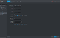
Door Config in DSS Express

Card Reader:Wiegand
| Port | Cable Color | Cable Name | Description | |
|---|---|---|---|---|
| CON1 | ||||
| White | 35px | D1 | Wiegand D1 input (connected to external card reader)/output (connected to controller). | |
| Green | 35px | D0 | Wiegand D0 input (connected to external card reader)/output (connected to controller). | |