How To Connect Relay Module
Contents
How to Connect a Relay Module
Pre-Requisites
- A Relay Module with input and ground options for your IP Camera's Alarm
- Cameras model: hdbw4221f-as with ALARM_OUT1 (Orange Wire), and ALARM_GND (Grey Wire)
- Power supply unit rated to power the relay (5v for this demo)
- Alarm output device (and an optional power supply)
Overview
Please check all of your systems (IPC, Relay Module, and Alarm Output Device's) power requirements and specifications before plugging them in without any understanding of how it works, as this can result in possible electrical fires or even the death of your systems (or persons).
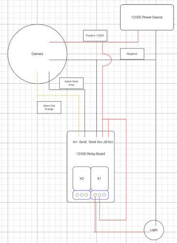
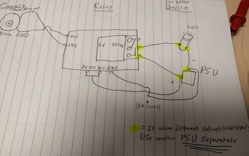
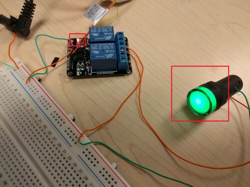
If you are familiar with wiring low voltage alarm systems like the one we are featuring here, then here are two wiring diagram examples, use discretion when wiring voltages above 12VDC 1amp as the signal wires in your IP Camera have their own specified operating range. Notice the highlighted area, this diagram uses 1 5vDC power supply to supply the Relay Module, and the output device which is an LED.
How To Connect A Physical Buzzer
This Guide is intended for new beginners to this concept:
1. This feature uses both the orange (alarm out) and the gray (ground) wires in order to signal out (a 100ohm closed circuit) to a relay module or control device. This setup is typically different than most low voltage electrical since the camera itself does not have a relay on board (no NO/NC/COM wires). Because of this you will need to acquire a relay module with a signal input. These can be found for raspberri Pi's and arduino's, or for this demo if a Sainsmart 5vDC double relay module.
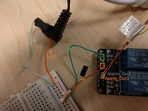
2. Start with wiring the 5vDC power supply to the relay board. Positive is linked to JD-VCC and VCC, and Negative is linked to GND on the pinout powering the relay module's action.
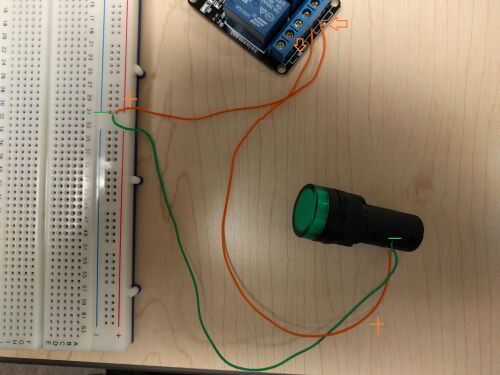
3. Now wire in your device that your are trying to control into the main terminal block of the Relay, and supply the required power (I used the same 5vDC psu since the light works with 5vDC). If you are using a higher powered circuit, please isolate the circuit to just the power supply, relay module terminal, and your device. Since the light is going to be triggered via ALARM_OUT1 on the IP Camera, I will wire the circuit normally open (NO) by plugging the circuit into the select terminals below. If you want the circuit to be normally closed (NC) please take the left wire and move it to the right terminal.
4. Once your 5vDC power supply is plugged in, attach the camera's ALARM_GND (gray) wire to GND on the control pinout, and ALARM_OUT1 (orange) wire to IN1.
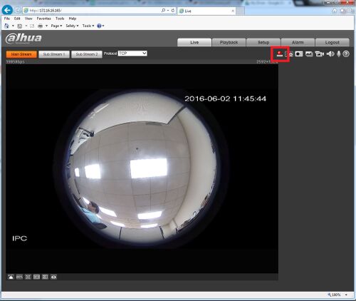
5. Now power up and log into the camera and trigger the alarm out one via the manual toggle button seen below
6. Your device should now be activated and you will audibly hear the relay click the circuit on (unless you are using a solid state circuit).
