Access Control/How To Connect Electronic Buzzer
Contents
How to Connect Electronic Buzzer
Description
This Article will show you how to wire and setup an alarm output device to the recorder.
Prerequisites
- NVR/HCVR/DVR with Alarm IN and OUT relay functionality
- Alarm input, in this case: Magnetic Sensor
- Alarm output, in this case: Electronic Buzzer
- Power supply unit rated for the Electronic Buzzer (and the NVR/HCVR/DVR)
- Power blocks (should come with NVR/HCVR/DVR
Please check all of your systems (NVR/HCVR/DVR PSU and Electronic Buzzer) power requirements and specifications before plugging things in without any understanding of how it works, as this can result in possible electrical fires or even the death of your systems (NVR/HCVR/DVR PSU and Electronic Buzzer).
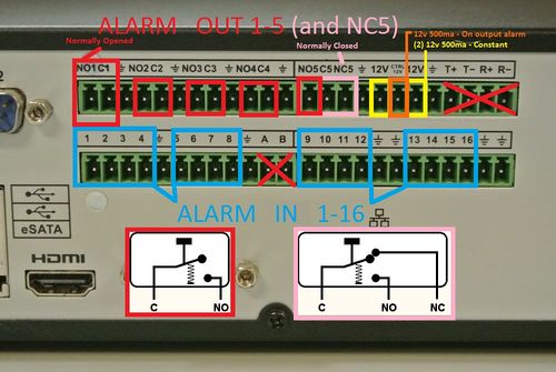
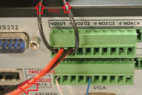
If you are familiar with wiring low power alarm systems like the one we are featuring here, then here is the back panel wiring diagram, use discretion when wiring voltages above 12VDC 1amp as the relays in your NVR/HCVR/DVR have their own specified operating range.
Video Tutorial
Step by Step Instructions
This Guide is intended for new beginners to this concept:
1. Wiring the Magnetic Sensor for ALARM IN 1
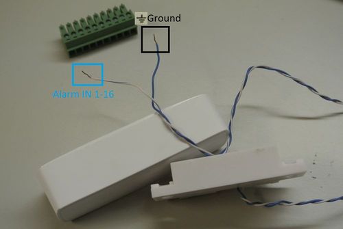
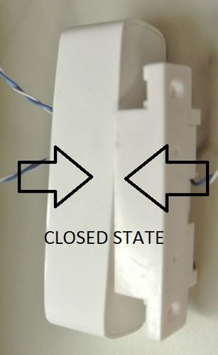
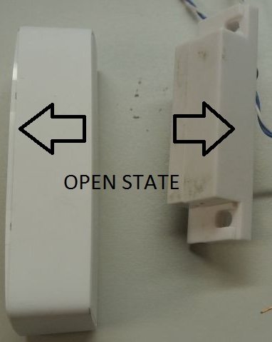
a. Here is your Magnetic sensor such as one used for a door. Please read the product guide for this sensor to determine which lead is the low power positive (ALARM IN 1 or "1") and which lead is the Negative/Ground ⏚ in the event that the sensor is unidirectional and not bidirectional.
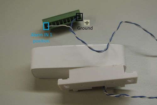
b. Plug the positive lead into your power block corresponding to ALARM IN 1 (refer to the first picture on the page for a diagram reference), and negative into any corresponding Negative/Ground ⏚ on the block.
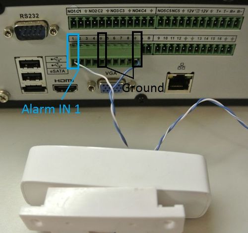
c. Plug the block into the ALARM IN section of your NVR/HCVR/DVR and check if the wires correspond to the correct pinout.
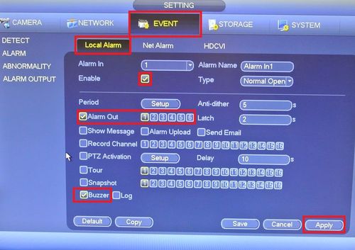
d. Now use this setup on your NVR/HCVR/DVR to test, make sure to click apply.
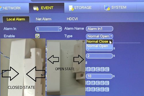
e. If you want to set the alarm circuit to open or close refer to this picture.
f. open or close your alarm IN1 circuit (move the magnet close or away from the device) and now your NVR/HCVR/DVR should signal it's audible buzzer out.
2. Wiring the Electronic Buzzer for ALARM OUT 1
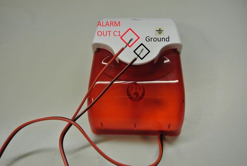
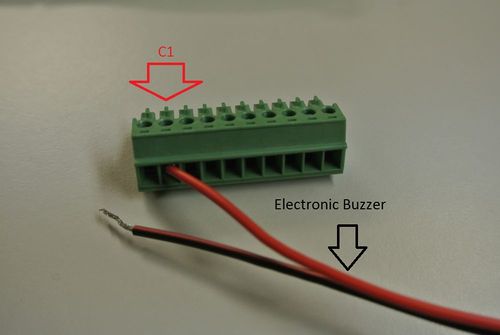
a. Here is your Electronic Buzzer, please read the product guide for this sensor to determine which lead is the power positive (ALARM OUT C1) and which lead is the Negative/Ground ⏚ in the event that the alarm is unidirectional and not bidirectional.
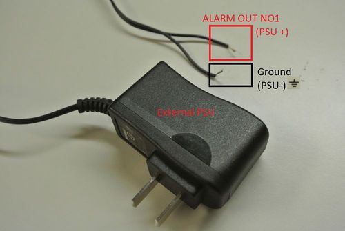
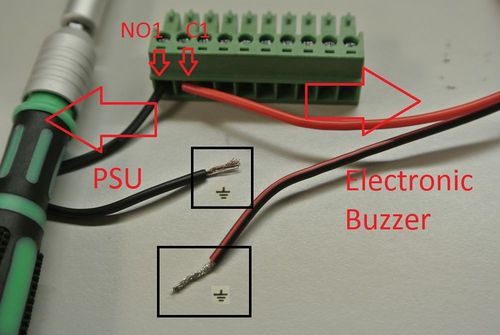
b. Also refer to the power requirements and specifications in order to make sure you are using the proper power supply unit for this device. Also Identify your power supply leads PSU+ and PSU- or Negative/Ground ⏚. PSU+ will go to ALARM OUT NO1.
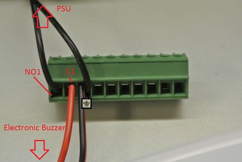
c. Take the Electronic Buzzer and seat the positive lead it into the power block corresponding to ALARM OUT C1
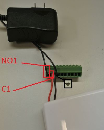
d. Take the PSU and seat the positive lead it into the power block corresponding to ALARM OUT NO1
e. Now seat both the PSU and Electronic Buzzer's Negative/Ground ⏚ leads into any of the corresponding alarm out Negative/Ground ⏚ terminals on the NVR/HCVR/DVR
f. Now double check and make sure you have everything setup according to all of your device's (NVR/HCVR/DVR PSU and Electronic Buzzer) specifications. Also check that the leads are seated properly in the power block and are making full metal to metal contact with the power block.
g. Now Connect the power block to the corresponding ALARM OUT area, and plug in your PSU
h. For testing purposes use this setup on your NVR/HCVR/DVR to make sure your setup works.
i. Now trigger you magnetic sensor and you should hear the NVR/HCVR/DVR's Buzzer, and also now your Electronic Buzzer should be alarming out.
Now you know how to setup both alarm inputs (magnetic sensor) and powered alarm outputs (Electronic Buzzer)! Please check all of your systems (NVR/HCVR/DVR PSU and Electronic Buzzer) power requirements and specifications before plugging things in without any understanding of how it works, as this can result in possible electrical fires or even the death of your systems (NVR/HCVR/DVR PSU and Electronic Buzzer).
