Difference between revisions of "Accessories/EoC"
(→Infographs) |
|||
| Line 32: | Line 32: | ||
|} | |} | ||
[[File:Rewire2022-01-28_140916.png|800px]] | [[File:Rewire2022-01-28_140916.png|800px]] | ||
| + | <br> | ||
| + | <span style=color:red;font-style:italic;font-weight:bold>Note: Please avoid cutting any of the EoC devices, you can also cut the cables on the network switch's side where a regular Ethernet cable is connected on the switch.</span> | ||
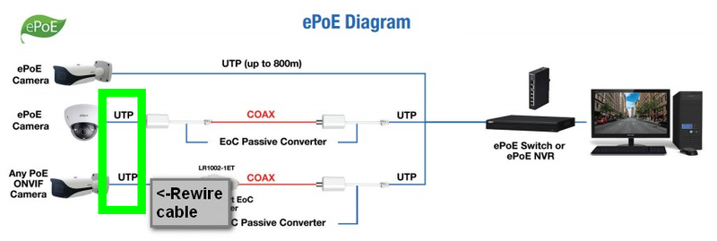
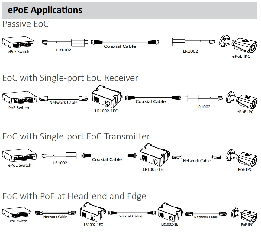
==Infographs== | ==Infographs== | ||
[[file:ePOE_Infograph.jpg]] | [[file:ePOE_Infograph.jpg]] | ||
| − | |||
| − | |||
[[file:EPOE_Infograph(replacement).png]] | [[file:EPOE_Infograph(replacement).png]] | ||
Latest revision as of 21:35, 18 November 2022
EoC
Diagram
Note: If multiple cameras on the same switch do NOT work, change the wiring diagram of the network cable to match the below diagram
| Pin | Pair | Wire | Color |
|---|---|---|---|
| 1 | 2 | 1 | |
| 2 | 2 | 2 | |
| 3 | 3 | 1 | |
| 4 | N/A | N/A | EMPTY |
| 5 | N/A | N/A | EMPTY |
| 6 | N/A | N/A | |
| 7 | N/A | N/A | EMPTY |
| 8 | N/A | N/A | EMPTY |

Note: Please avoid cutting any of the EoC devices, you can also cut the cables on the network switch's side where a regular Ethernet cable is connected on the switch.

