Difference between revisions of "Video Intercom/How To Add A Magnetic Lock To A VTO2111D-WP"
| Line 7: | Line 7: | ||
- Network connection to VTO | - Network connection to VTO | ||
===Video Instructions=== | ===Video Instructions=== | ||
| − | + | ||
===Step by Step Instructions=== | ===Step by Step Instructions=== | ||
1. Log into the VTO211D-WP's web interface through Internet Explorer (default login: admin /pw: admin). Navigate to Local Config -> A&C Manager and configure this page. '''Unlock Responding Interval''' is the amount of time between unclo | 1. Log into the VTO211D-WP's web interface through Internet Explorer (default login: admin /pw: admin). Navigate to Local Config -> A&C Manager and configure this page. '''Unlock Responding Interval''' is the amount of time between unclo | ||
| − | |||
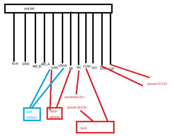
2. Now wire your door controlled using the diagram below. | 2. Now wire your door controlled using the diagram below. | ||
[[File:QQ图片20170711104144.png|600x600px]] | [[File:QQ图片20170711104144.png|600x600px]] | ||
| − | |||
| − | |||
3. After wiring, please test using the door unlock function, or wire in a push button for testing. | 3. After wiring, please test using the door unlock function, or wire in a push button for testing. | ||
Revision as of 07:49, 15 July 2017
Contents
How to add a Magnetic Lock to a VTO2111D-WP
Description
The VTO2111D-WP features a relay (NO/NC/COM) that can be activated when using the unlock door option. Please read below for step by step instructions on how to add a magnetic lock to a VTO211D-WP
Prerequisites
- Magnetic lock and power supply - VTO211D-WP - Network connection to VTO
Video Instructions
Step by Step Instructions
1. Log into the VTO211D-WP's web interface through Internet Explorer (default login: admin /pw: admin). Navigate to Local Config -> A&C Manager and configure this page. Unlock Responding Interval is the amount of time between unclo
2. Now wire your door controlled using the diagram below.
3. After wiring, please test using the door unlock function, or wire in a push button for testing.
