Video Intercom/How To Add A VTH1660CH To A VTO1210C-X
| Icon | Name | Generation | Technology | SIP 2.0 | Example Device 1 | Example Device 2 | Identifying Characteristic | PC Software | Mobile App |
|---|---|---|---|---|---|---|---|---|---|
| Gen1-IP | Gen 1 | IP | Non-SIP | VTH1550CH | VTO2111D-WP | No "-2" or "-S" | SmartPSS | gDMSS or iDMSS |
Contents
How To Add A VTH1660CH To A VTO1210C-X
Description
This Step by Step guide will provide instruction to setup A VTH1660CH To A VTO1210C-X via a LAN connection.
Prerequisites
- Power and network to VTH1660CH and VTO1210C-X
- Windows PC on the network
Video Instructions
Step by Step Instructions
VTO1210C-X Setup:
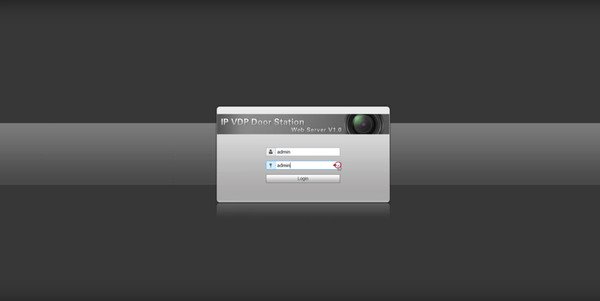
1. Log into the VTO via it's IP address using Internet Explorer (username:admin password:admin). To configure the VTO1210C's IP address please use the config tool to find the IP an change it. Alternatively press * and enter the admin code in (888888, but it can be modified) followed by # to access the menu. Select IP Setting to set the IP address, subnet mask, and gateway settings.
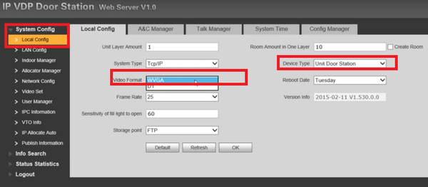
2. Under System Config-> Local Config set the video format to WVGA, Make sure your device type is set to Unit Door Station, then select OK.
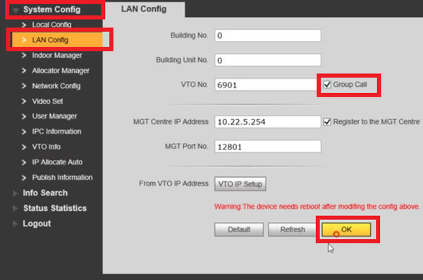
3. Select LAN Config and make sure "Group Call" is checked, then select OK.
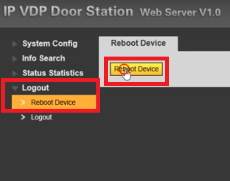
4. Select Logout-> Reboot Device and then select Reboot Device and then give the device 2-5 minutes to reboot and then log in again.
5. Select System Config-> Indoor Manager and then select Add, and add your VTH number(s), as well as any additional (but not required) information. This should conclude the Setup of the VTO1210C-X
VTH Setup
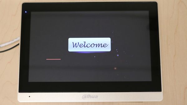
6. Plug a 12v DC power supply, and a network cable into the VTH1660CH, then wait for it to start.
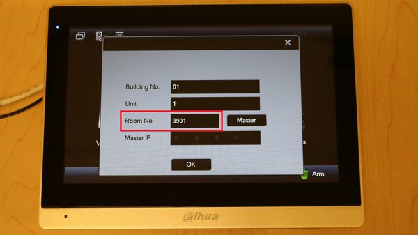
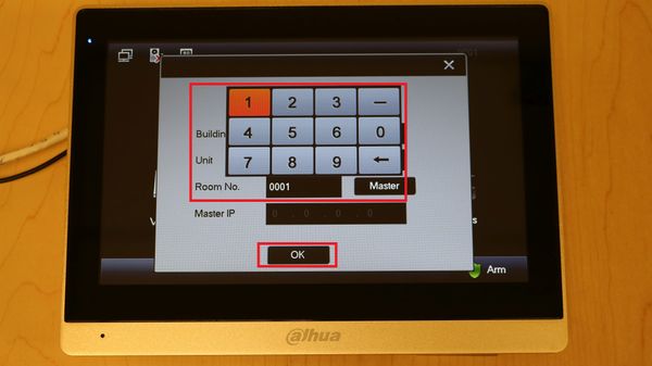
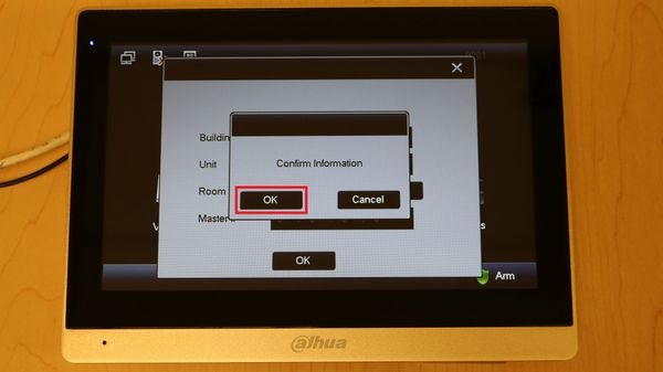
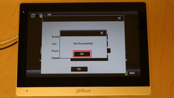
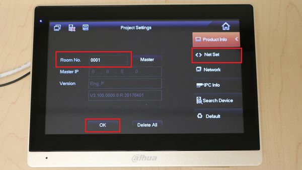
7. Once the VTH has booted you will be prompted by a screen, select the room number and enter 0001, or any 4 digit code you want the VTH to reside on.
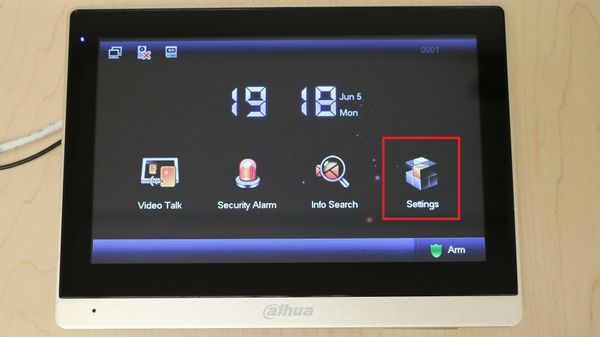
8. Now select Settings.
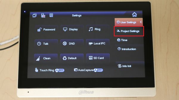
9. Now select Project Settings.
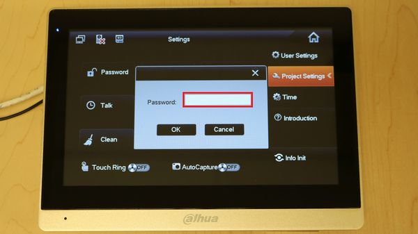
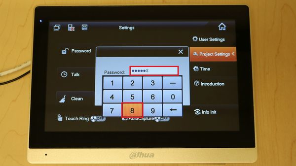
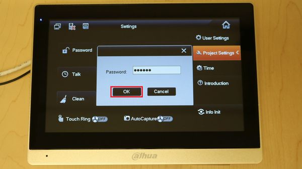
10. Select the password field.
11. Enter in "888888" as the password if the firmware is 2017 or newer, if not try one of these: 002236, 123456.
12. Once inside the Settings menu make sure you room number is four digits and has been added to the VTO. Now select Net Set.
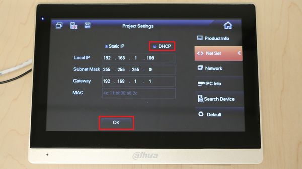
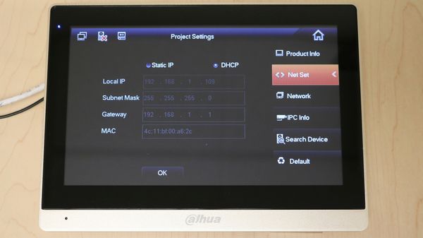
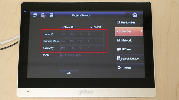
13. In the Net Set menu please assign the VTH an address, or if you have a router (or DHCP server) running on the network select DHCP and then OK.
Notice the change in the IP settings, then select Network on the right.
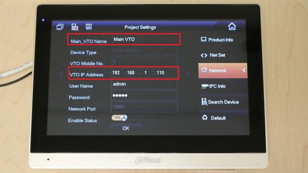
14. Once in this menu you can manually configure the network connection to your VTO(s). This feature is here for network without a router (or DHCP server), however it still applies to a network with one.
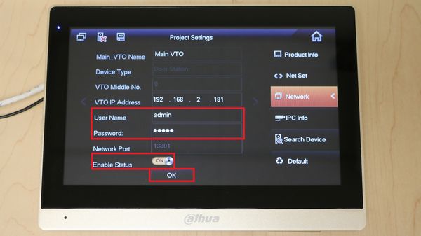
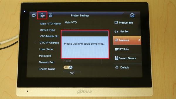
If you plan on manually entering the VTO(s) information, then make sure you are using the correct IP address, user name, password, and also check that the Enable Status slider is switched to ON, then select OK.
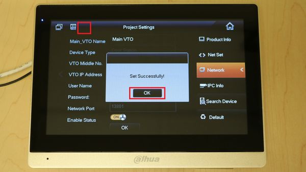
Wait until the setup completes, and notice the VTO offline icon in the top left corner of the screen.
Once the icon has gone away, you have now establish a network connection with the VTO.
15. If you select Search Device on the bottom right corner then you will see a green VTO icon next to your Main VTO, you can also use this menu yo connect to VTO's. Typically these devices should work, however if they don't please reboot both the VTH and VTO and try again.
Test Call
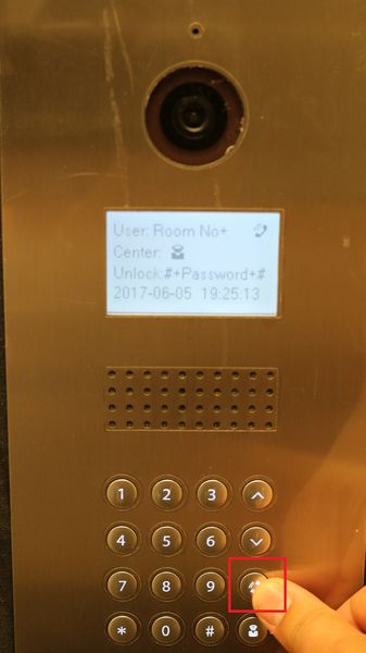
16. Use the VTO's Call button to access the list of added VTH's.
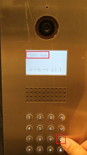
17. Use the up and down arrows to navigate a list of Room Numbers and Nicknames. Once you have found the desired VTH to call, press the call button again to place the call.
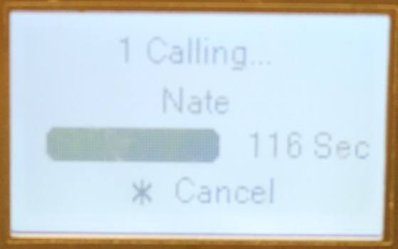
18. Once the call has been placed notice you will have a limited amount of time for the call to be placed, this setting can be changed in the VTO's web interface.
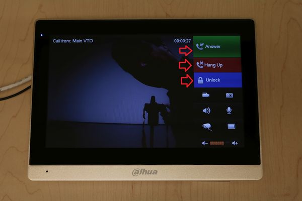
19. On the VTH you will notice a ring tone that plays along with the camera feed from the VTO once a call has been placed to it. This view is used to verify the identity of the person trying to access the door by the VTO. From here you have several options:
- Answer - This will enable a two way talk session
- Hang up - This will end the call
- Unlock - This will trigger the relay output on the VTO (typically wired to a door)
