Video Intercom/SIP 2.0/Stand Alone VTH and VTO Setup
Contents
Stand Alone VTH and VTO Setup
| Icon | Name | Generation | Technology | SIP 2.0 | Example Device 1 | Example Device 2 | Identifying Characteristic | PC Software | Mobile App |
|---|---|---|---|---|---|---|---|---|---|
| Gen2-SIP2.0-IP | Gen 2 | IP | SIP 2.0 | VTH1550CH-S | DHI-VTO2000A-S | "-S" at end of model name | DSS or DSS Express S | DSS Mobile for VDP | |
| Gen2-SIP2.0-2Wire | Gen 2 | 2-Wire | SIP 2.0 | DHI-VTH1550CHW-2-S | DHI-VTO2000A-2-S | "-2-S" at end of model name | DSS or DSS Express S | DSS Mobile for VDP |
Description
This guide will show how to setup a VTO and VTH device on a network
This guide will use a VTO2000A-S and VTH1510-S
Prerequisites
- VTO and VTH initialized and set up on network
- VTO and VTH log in information
Video Instructions
Step by Step Instructions
VTO Setup
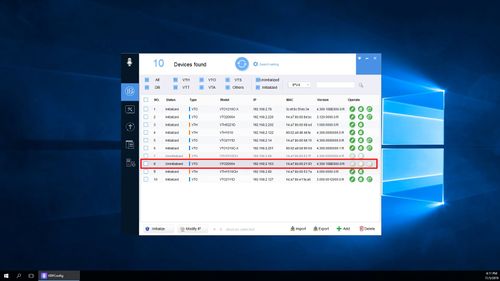
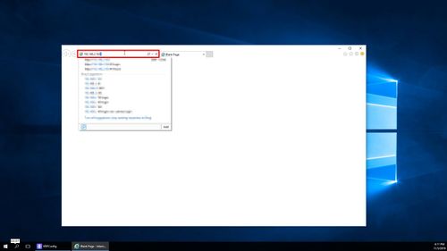
1. Log into the web interface of the VTO by entering the IP
You can find the current IP of the VTO by using VDPConfig from a local computer
Enter the IP into Internet Explorer
2. The Device Initialization will appear if this device has not been initialized
Device Initialization Steps:
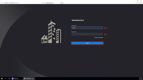
3. Log into the device by entering the Username and Password and click Login
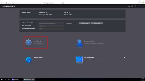
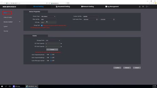
4. Click Local Setting
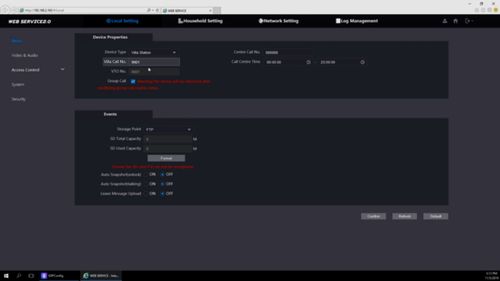
5. Under Basic settings, confirm the information being used.
In this example we will use the default
Villa Call No. = 9901
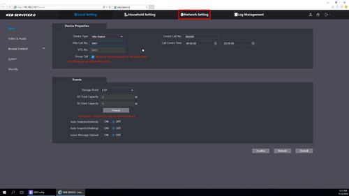
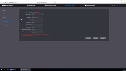
6. Now the SIP function must be enabled and configured
Click Network Settings
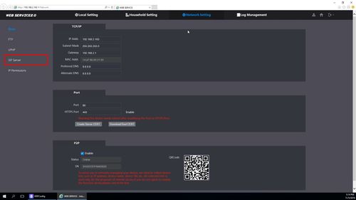
7. Click SIP Server
8. In this example, the VTO device itself will act as the SIP server
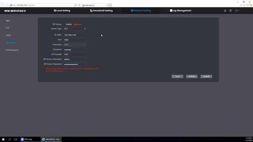
To make changes to SIP Server settings, start by unchecking the box next to Enable
The fields can now be edited
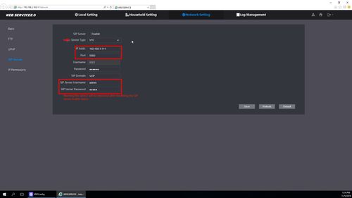
- Server Type - VTO
- IP Address - IP Address of VTO device , in this example 192.168.2.163
- Port - 5060 - Leave at default
- SIP Server Username - Username for VTO
- SIP Server Password - Password for VTO
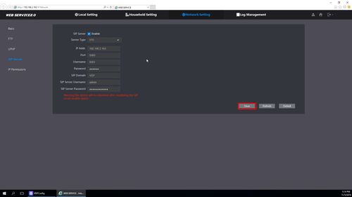
9. Once all information has been entered, check the box to enable SIP Server
10. Click 'Save' to save settings
VTH Setup
1. Power on the VTH
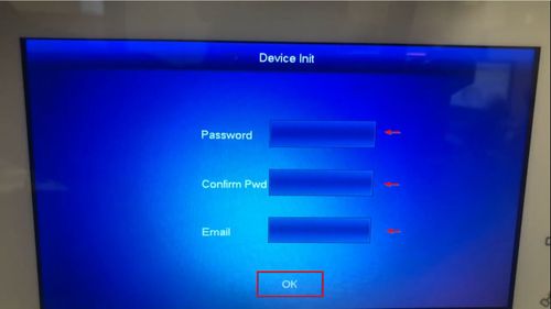
Device Initialization will appear if this device has not been initialized
- Password - create a password for the device
- Confirm Pwd - confirm created password
- Email - email address used for password recovery
Select OK once all information has been entered
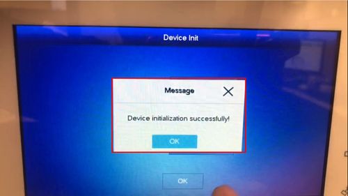
2. A message will confirm successful device initialization
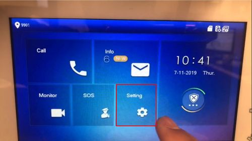
3. From the Main Menu 'long press' or tap and hold the 'Setting' button for over 6 seconds to enter Advanced Settings
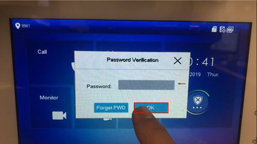
4. Enter the password for the device and select OK
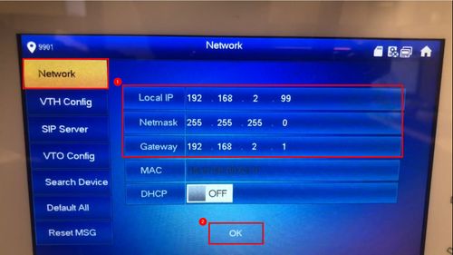
5. Network
Confirm the IP information for the VTH device
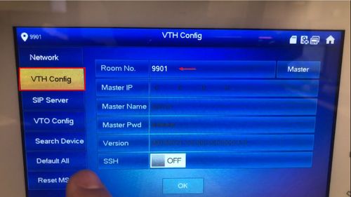
6. VTH Config
Tap the field next to 'Room No.' to change the setting
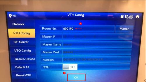
The VTH Room No. will be the VTO's Villa Call Number with an added '#0'
In this example we will use the VTO's Call No. of 9901 + #0
9901#0
Tap OK once the information has been entered
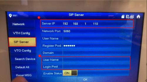
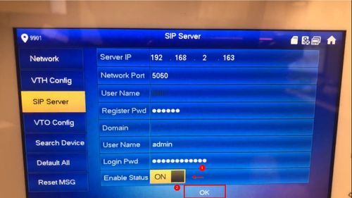
7. SIP Server
In this example the VTO has been configured to act as the SIP Server, so the VTO device information will be entered in this section in the highlighted fields
All other fields should be left at their default settings
- Server IP - IP Address of VTO
- User Name - User Name for VTO
- Login Pwd - Password for VTO
8. Once the information has been entered
Tap the toggle next to 'Enable Status' to On
Tap OK to save settings
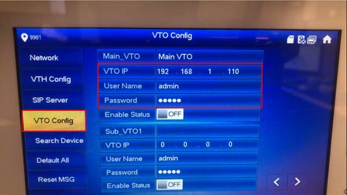
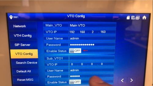
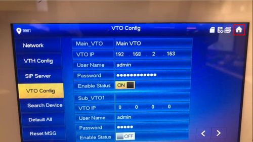
9. VTO Config
Enter the information for the VTO device:
10. Once the information has been entered
Tap the toggle next to 'Enable Status' to On
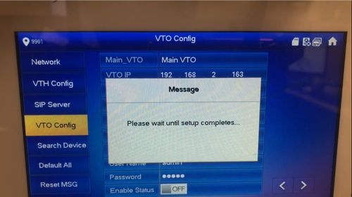
11. A message will pop up to confirm
12. The VTH is now configured
Tap the Home icon in the top right to return to the Home screen
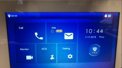
13. Once the devices have been both configured properly it can take a few minutes for the devices to complete the connection between the devices
You can monitor the status of the connection by checking the upper right corner of the VTH
This icon will be displayed when there is no active connection to the VTO:
14. Once the icon has been cleared then the devices should be ready to communicate.
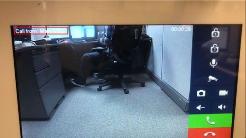
15. Test a call by pressing the call button on the VTO and you should receive a call at the VTH
