Difference between revisions of "Traffic/Initial Setup"
(→Step by Step Instructions) |
|||
| (16 intermediate revisions by 2 users not shown) | |||
| Line 1: | Line 1: | ||
| − | =ITC237 | + | =ITC215 and ITC237 Initial Setup= |
==Description== | ==Description== | ||
==Prerequisites== | ==Prerequisites== | ||
| Line 22: | Line 22: | ||
</gallery> | </gallery> | ||
| − | ==Video Instructions== | + | ==Generation 2 Chipset Instructions== |
| + | ===Video Instructions=== | ||
| + | <embedvideo service="youtube">https://www.youtube.com/watch?v=uA2TyheR-mc</embedvideo> | ||
| + | |||
| + | ===Step by Step Instructions=== | ||
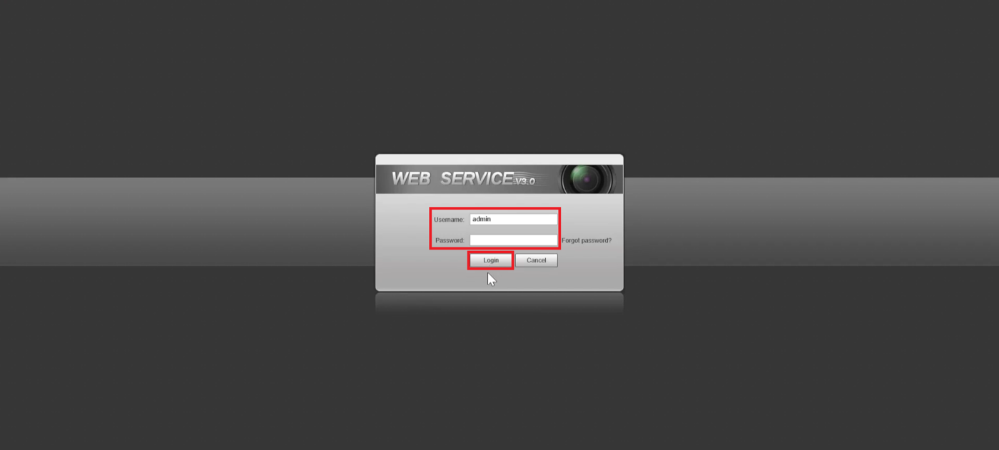
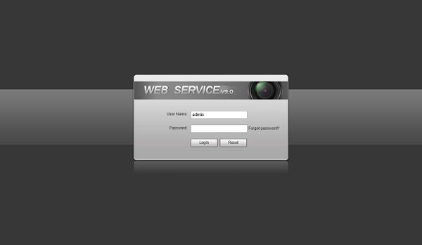
| + | 1. Log into the Web UI of the camera by typing the IP into a web browser. | ||
| + | <br>Then enter the username/password and click '''Login''' | ||
| + | |||
| + | [[File:ITC215ITC237Gen2Setup1.png|1400px]] | ||
| + | |||
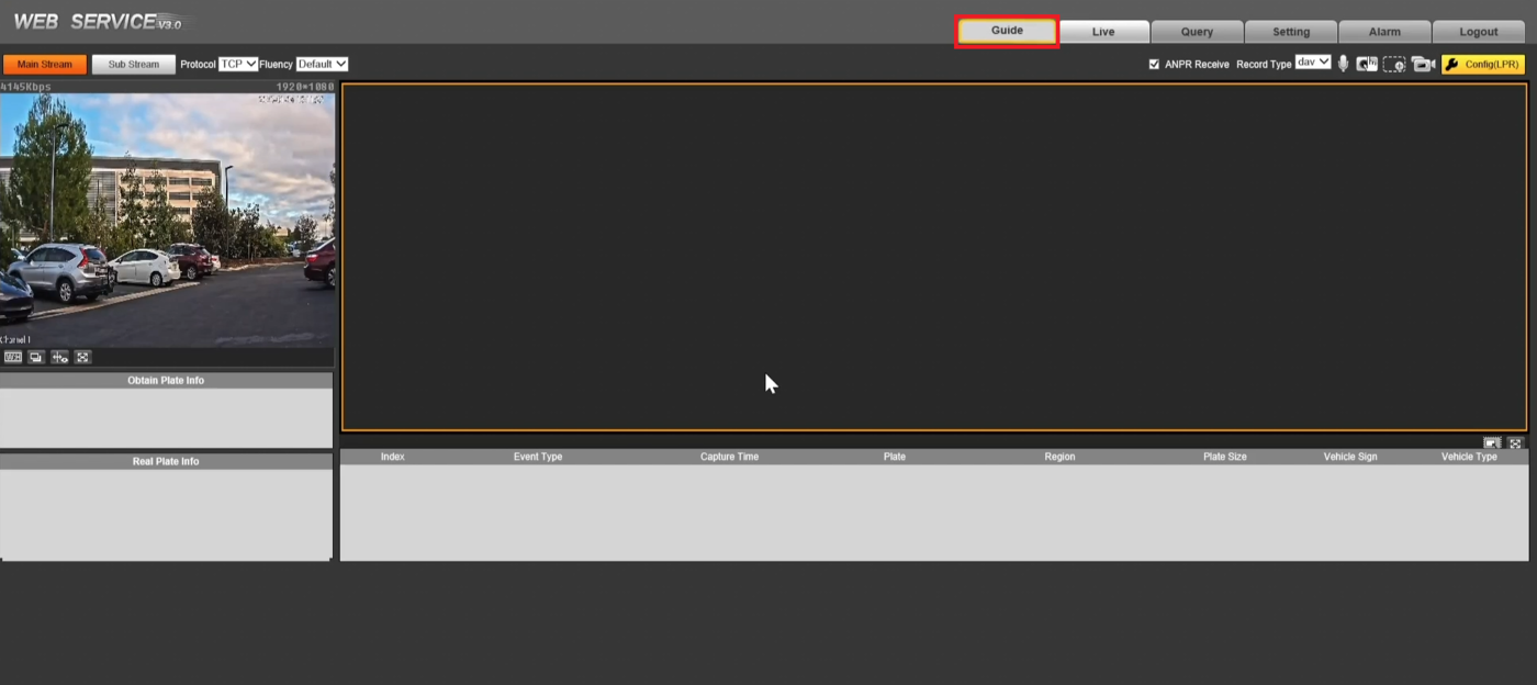
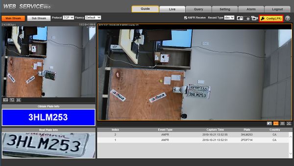
| + | 2. Click on the '''Guide''' tab at the top | ||
| + | |||
| + | [[File:ITC215ITC237Gen2Setup2.png|1400px]] | ||
| + | |||
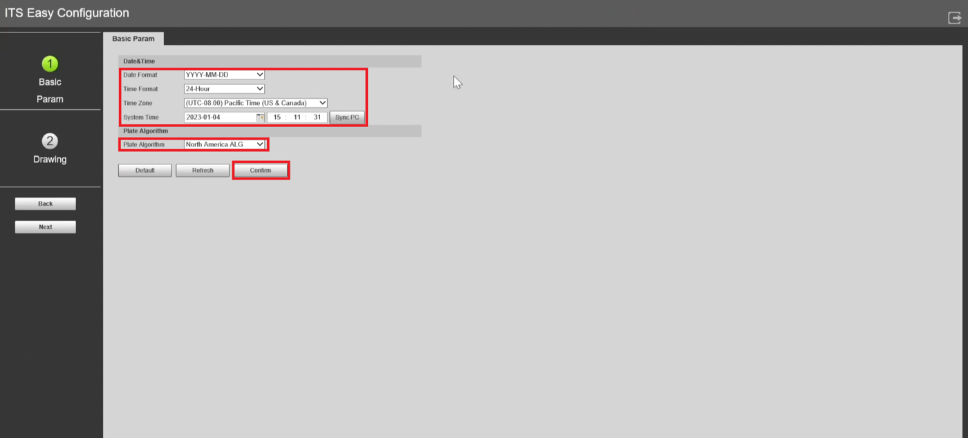
| + | 3. Set the Date and Time settings to match your location's Date, Time, and Timezone. | ||
| + | <br>Then click on the '''Plate Algorithm''' drop-down and select the appropriate option for your location. | ||
| + | <br>Click '''Confirm''' | ||
| + | |||
| + | [[File:ITC215ITC237Gen2Setup3.png|1400px]] | ||
| + | |||
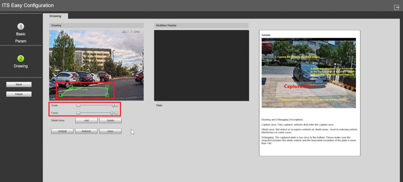
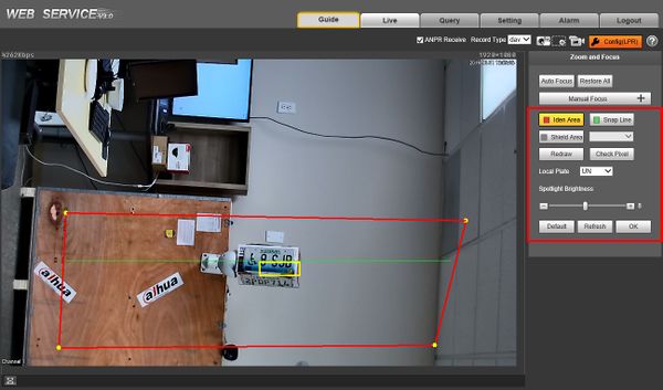
| + | 4. Adjust the the '''Zoom''' and '''Focus''' sliders until the camera is at the right zoom level for the physical setup. | ||
| + | <br>Click on the '''Capture Area''' box in the '''Drawing''' live view area and move it around to the desired location for capturing license plates. | ||
| + | <br>Adjust the size and shape of the '''Capture Area''' box by dragging the four corners to the appropriate location on the live view | ||
| + | |||
| + | [[File:ITC215ITC237Gen2Setup4.png|1400px]] | ||
| + | |||
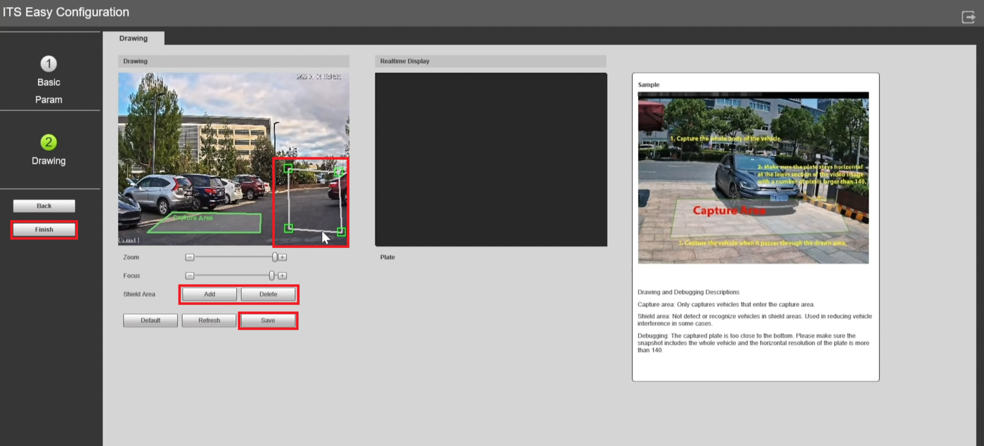
| + | 5. Optionally you can add Shield Areas that avoid looking for license plates. | ||
| + | <br>To add a Shield Area click on the '''Add''' button next to '''Shield Area'''. | ||
| + | <br>Then left click multiple times on the live view to draw the Shield Area box. | ||
| + | <br>If you want to delete a Shield area, left click on it in the live view and then click on '''Delete''' | ||
| + | <br>When you are done making changes click on '''Save''' at the bottom and then '''Finish''' on the left | ||
| + | |||
| + | [[File:ITC215ITC237Gen2Setup5.5.png|1400px]] | ||
| + | |||
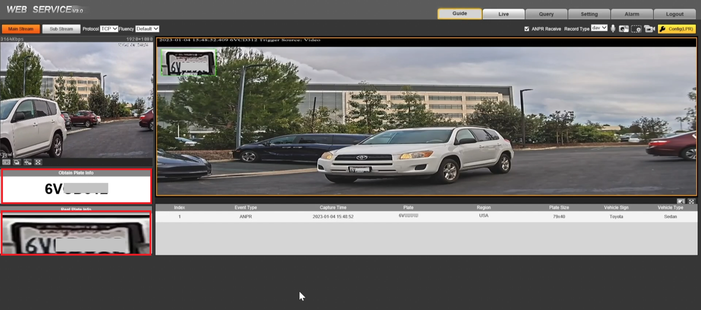
| + | 6. Drive a vehicle in front of the LPR camera through the detection area to test the license plate capture and recognition setup. | ||
| + | <br>If everything is setup correctly the license plate number in the picture of the license plate will match the text in the '''Obtain Plate Info''' field | ||
| + | |||
| + | [[File:ITC215ITC237Gen2Setup6.png|1400px]] | ||
| + | |||
| + | ==Generation 1 Chipset Instructions== | ||
| + | ===Video Instructions=== | ||
<embedvideo service="youtube">https://youtu.be/x7HgmYMv2gQ</embedvideo> | <embedvideo service="youtube">https://youtu.be/x7HgmYMv2gQ</embedvideo> | ||
===Video Overview-Drone Flyover=== | ===Video Overview-Drone Flyover=== | ||
| Line 29: | Line 69: | ||
<embedvideo service="youtube">https://youtu.be/gsDAZ7QxobQ</embedvideo> | <embedvideo service="youtube">https://youtu.be/gsDAZ7QxobQ</embedvideo> | ||
| − | ==Step by Step Instructions== | + | ===Step by Step Instructions=== |
1. Log into the Web UI of the camera by typing the IP into a web browser. | 1. Log into the Web UI of the camera by typing the IP into a web browser. | ||
| Line 36: | Line 76: | ||
[[File:ITC237_Physical_Setup_0.jpg|600px]] | [[File:ITC237_Physical_Setup_0.jpg|600px]] | ||
| − | 2. Click | + | 2. Click Config (LPR) to enter the configuration menu for the LPR function |
[[File:ITC237_Physical_Setup_0-1.jpg|600px]] | [[File:ITC237_Physical_Setup_0-1.jpg|600px]] | ||
| − | 3. | + | 3. The LPR Config menu will be displayed |
| + | |||
| + | [[File:ITC237_Physical_Setup_0-2.jpg|600px]] | ||
| + | |||
| + | To configure the LPR function use the interface: | ||
| + | *[[File:iden_area.jpg|100px]] - Region - Set region for detection, region is within the red line. | ||
| + | *[[File:snap_line.jpg|100px]] - Detect Line - Detect line for trigger of snapshot, detect line is green. | ||
| + | *[[File:shield_area.jpg|100px]] - Shield Area - Set shield area to not identify vehicle plates, Up to 2 shield areas, Shield area is within the grey box. | ||
| + | *[[File:redraw.jpg|100px]] - Redraw - Click to delete current config | ||
| + | |||
| + | |||
| + | 4. Adjust the plate snapshot position to be in the yellow box. | ||
| + | |||
| + | [[File:ITC237_Physical_Setup_1_-_Correct.jpg|600px]] | ||
| + | |||
| + | 5. Continue to make adjustments with the detection zone AND physically moving the camera until the yellow box is right on point with the expected license plate position. | ||
| + | |||
| + | Physically adjust the camera to complete proper setup. | ||
| + | |||
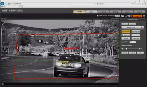
| + | Ensure the box matches the actual plate position and size in the video. | ||
| − | [[File: | + | [[File:ITC237_Physical_Setup_1_-_Incorrect.jpg|600px]] |
| − | + | ===Step by Step Instructions - Guide=== | |
| − | + | {{Template:LPR_Camera_Guide_Setup}} | |
==Troubleshoot== | ==Troubleshoot== | ||
Latest revision as of 23:31, 18 January 2023
Contents
ITC215 and ITC237 Initial Setup
Description
Prerequisites
- 150x50 License Plate pixel size or higher from snapshot images
- Car Traffic = 25MPH or Less
Camera Angle
Pixel Density
Generation 2 Chipset Instructions
Video Instructions
Step by Step Instructions
1. Log into the Web UI of the camera by typing the IP into a web browser.
Then enter the username/password and click Login
2. Click on the Guide tab at the top
3. Set the Date and Time settings to match your location's Date, Time, and Timezone.
Then click on the Plate Algorithm drop-down and select the appropriate option for your location.
Click Confirm
4. Adjust the the Zoom and Focus sliders until the camera is at the right zoom level for the physical setup.
Click on the Capture Area box in the Drawing live view area and move it around to the desired location for capturing license plates.
Adjust the size and shape of the Capture Area box by dragging the four corners to the appropriate location on the live view
5. Optionally you can add Shield Areas that avoid looking for license plates.
To add a Shield Area click on the Add button next to Shield Area.
Then left click multiple times on the live view to draw the Shield Area box.
If you want to delete a Shield area, left click on it in the live view and then click on Delete
When you are done making changes click on Save at the bottom and then Finish on the left
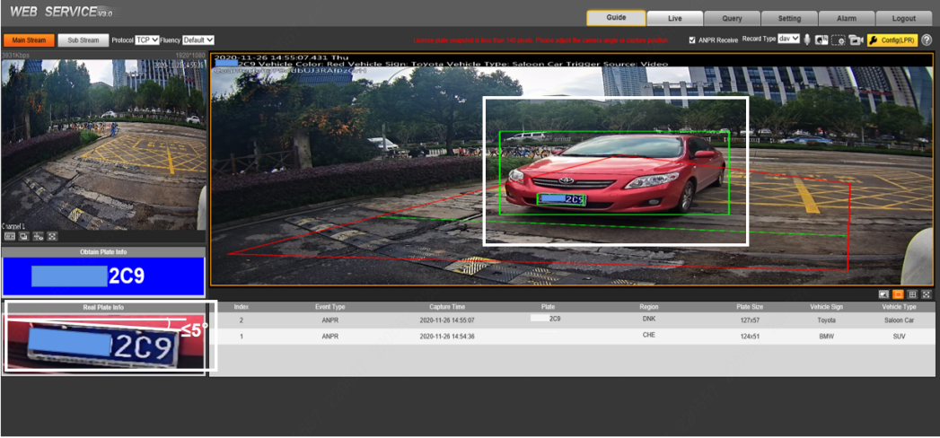
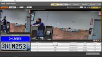
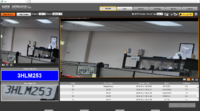
6. Drive a vehicle in front of the LPR camera through the detection area to test the license plate capture and recognition setup.
If everything is setup correctly the license plate number in the picture of the license plate will match the text in the Obtain Plate Info field
Generation 1 Chipset Instructions
Video Instructions
Video Overview-Drone Flyover
Step by Step Instructions
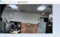
1. Log into the Web UI of the camera by typing the IP into a web browser.
Enter the username/password and click Login
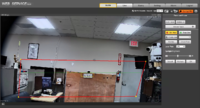
2. Click Config (LPR) to enter the configuration menu for the LPR function
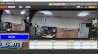
3. The LPR Config menu will be displayed
To configure the LPR function use the interface:
 - Region - Set region for detection, region is within the red line.
 - Detect Line - Detect line for trigger of snapshot, detect line is green.
 - Shield Area - Set shield area to not identify vehicle plates, Up to 2 shield areas, Shield area is within the grey box.
 - Redraw - Click to delete current config
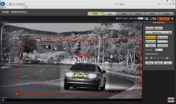
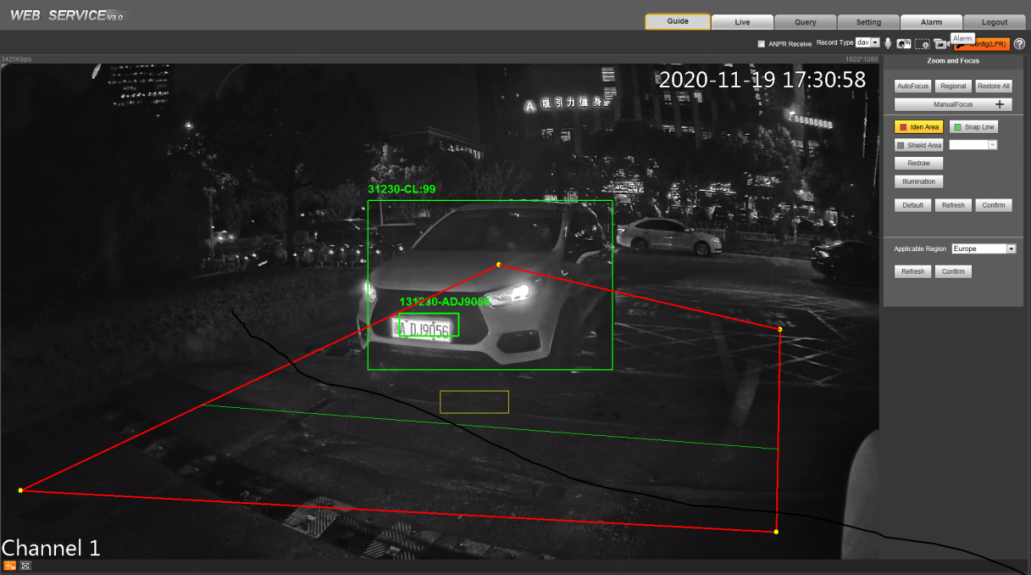
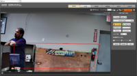
4. Adjust the plate snapshot position to be in the yellow box.
5. Continue to make adjustments with the detection zone AND physically moving the camera until the yellow box is right on point with the expected license plate position.
Physically adjust the camera to complete proper setup.
Ensure the box matches the actual plate position and size in the video.
Step by Step Instructions - Guide
The Guide interface is useful to configure the correct settings for license plate capture
Log into the Web UI of the camera by typing the IP into a web browser.
Enter the username/password and click Login
- Click the Guide tab.
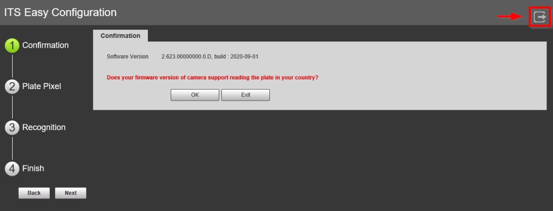
On the Guide interface, you can configure capture scenarios. You can click at at the upper-right corner of Guide interface to exit at anytime.
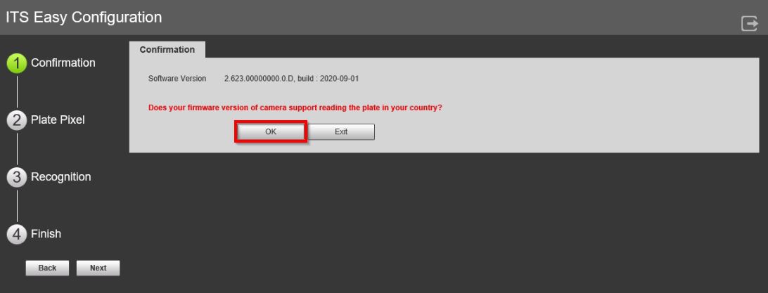
1. Confirmation
- Confirm the Software Version is the latest (Visit the Product page for latest firmware version - Link), and then click OK.
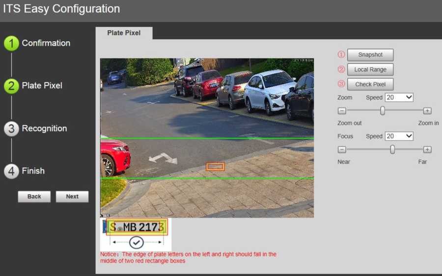
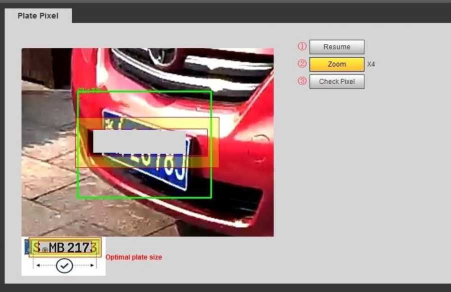
2. Plate Pixel
- You can check whether the video image is properly zoomed and focused by checking the plate pixel.
Below the video frame there is an example of the optimal plate positioning:
Use the Pixel Plate settings to adjust the camera for zoom and focus
- Drag the Zoom and Focus bar to adjust the image properly
- Position a vehicle/plate into the camera's view
Click Snapshot to take a snapshot of the plate (Snapshot button will become Resume)
- Drag the yellow box to the position of the plate
- Click Local Range to zoom the picture by 2x or 4x zoom rate (if required)
- Continue to adjust the position yellow box to make it optimal plate size:
If the plate within the yellow box is larger than the optimal plate size in the example, zoom out the video image; if smaller, zoom in the video image.
It may also require reviewing proper mounting requirements/positions if any softw3are adjustments do not allow for optimal plate positioning.
- Once the plate is in optimal position, click Check Pixel. Click Yes to confirm.
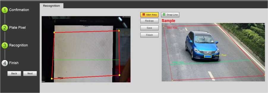
3. Recognition
- This section will configure the recognition/identification area for detection of license plates. The sample image can be used as a reference
A sample Identification Area and Snap Line will be displayed.
To clear or Redraw these Click either Iden Area ![]() or Snap Line
or Snap Line ![]()
To create new Recognition settings:
Click and draw 4 lines on the video frame to create a recognition area. Only plates in this area will be detected.
Draw snap line by dragging mouse on the area. The snap line must cross the area. Vehicles passing this line will trigger plate detection.
3) Click Save to complete the Setup.
Click Finish, exit Guide interface and enter Live interface.
Example at Live interface:
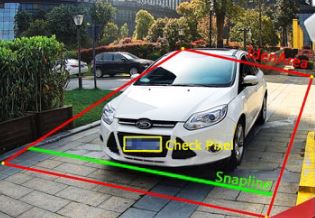
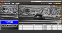
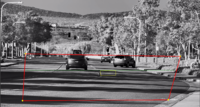
- Make sure the vehicle is within the red identification area line
- The green snap line is about 1/3 of the road
- Angle between the bottom of the license plate and the screen ≤5°
- The license plate has more than 140 pixels.
Troubleshoot
Working Examples
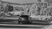
| Snapshot | Example of Interface | Current Configuration of Camera LPR |
|---|---|---|
|
|
|
