Difference between revisions of "Record/Basic/Alarm Out"
(→Physical Setup Instructions) |
|||
| (8 intermediate revisions by 3 users not shown) | |||
| Line 2: | Line 2: | ||
==Description== | ==Description== | ||
This feature will allow you to specify a range of time for a Dahua device to record when a physical alarm is triggered. | This feature will allow you to specify a range of time for a Dahua device to record when a physical alarm is triggered. | ||
| + | |||
| + | Alarm output circuit on the NVR is '''Normally Open''' by default. | ||
| + | |||
| + | The following can trigger an Alarm Out from a Dahua IP Camera with the appropriate alarm outputs: | ||
| + | *Motion Detection | ||
| + | *Video Tamper | ||
| + | *Scene Change | ||
| + | *Audio Detection | ||
| + | *IVS | ||
| + | *Face Detection | ||
| + | *Abnormality | ||
| + | **SD-Card | ||
| + | ***No DS-Card | ||
| + | ***SD Card Error | ||
| + | ***Capacity Warning | ||
| + | **Network | ||
| + | ***Disconnection | ||
| + | ***IP Conflict | ||
| + | **Illegal Access | ||
| + | |||
| + | The following can trigger an Alarm Out from a Dahua Recorder with the appropriate alarm outputs: | ||
==Physical Setup Instructions== | ==Physical Setup Instructions== | ||
<div class="toccolours mw-collapsible mw-collapsed"> | <div class="toccolours mw-collapsible mw-collapsed"> | ||
| − | [[File:Stobe_and_buzzer_physical_Alarm.JPG|250px]]<span style="font-size:180%;">'''Strobe and Buzzer'''</span> | + | [[File:Stobe_and_buzzer_physical_Alarm.JPG|250px]]<span style="font-size:180%;">'''Strobe and Buzzer(External Power)'''</span> |
<div class="mw-collapsible-content">{{Template:Alarm_Record_Physical_Alarm_Out}}</div> | <div class="mw-collapsible-content">{{Template:Alarm_Record_Physical_Alarm_Out}}</div> | ||
</div> | </div> | ||
| Line 33: | Line 54: | ||
[[File:Icon_for_type_SmartPSS.png|250px]]<span style="font-size:180%;">'''SmartPSS'''</span> | [[File:Icon_for_type_SmartPSS.png|250px]]<span style="font-size:180%;">'''SmartPSS'''</span> | ||
<div class="mw-collapsible-content">{{Template:Alarm_Out__SmartPSS}}</div> | <div class="mw-collapsible-content">{{Template:Alarm_Out__SmartPSS}}</div> | ||
| − | |||
| − | |||
| − | |||
| − | |||
| − | |||
| − | |||
| − | |||
| − | |||
| − | |||
| − | |||
| − | |||
| − | |||
| − | |||
| − | |||
| − | |||
</div> | </div> | ||
Latest revision as of 18:49, 21 December 2023
Contents
- 1 Alarm Out
- 1.1 Description
- 1.2 Physical Setup Instructions
- 1.3 Prerequisites
- 1.4 Step by Step Instructions
- 1.5 Instructions
- 1.6 Prerequisites
- 1.7 Video Instructions
- 1.8 Step by Step Instructions
- 1.9 Prerequisites
- 1.10 Video Instructions
- 1.11 Step by Step Instructions
- 1.12 Prerequisites
- 1.13 Video Instructions
- 1.14 Step by Step Instructions
- 1.15 Prerequisites
- 1.16 Video Instructions
- 1.17 Step by Step Instructions
- 1.18 Prerequisites
- 1.19 Video Instructions
- 1.20 Step by Step Instructions
Alarm Out
Description
This feature will allow you to specify a range of time for a Dahua device to record when a physical alarm is triggered.
Alarm output circuit on the NVR is Normally Open by default.
The following can trigger an Alarm Out from a Dahua IP Camera with the appropriate alarm outputs:
- Motion Detection
- Video Tamper
- Scene Change
- Audio Detection
- IVS
- Face Detection
- Abnormality
- SD-Card
- No DS-Card
- SD Card Error
- Capacity Warning
- Network
- Disconnection
- IP Conflict
- Illegal Access
- SD-Card
The following can trigger an Alarm Out from a Dahua Recorder with the appropriate alarm outputs:
Physical Setup Instructions
Prerequisites
Step by Step Instructions
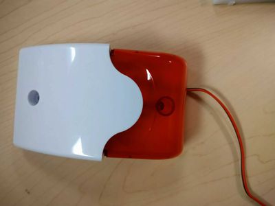
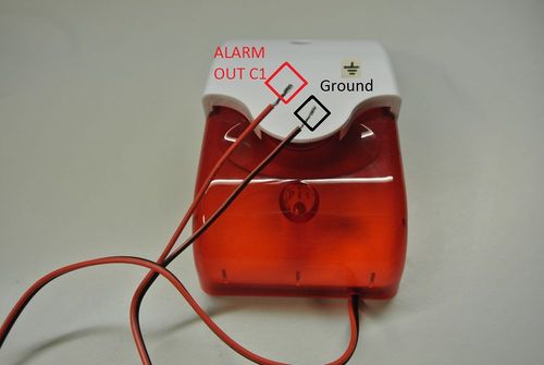
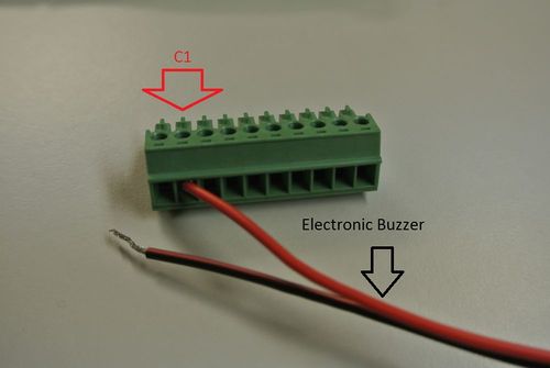
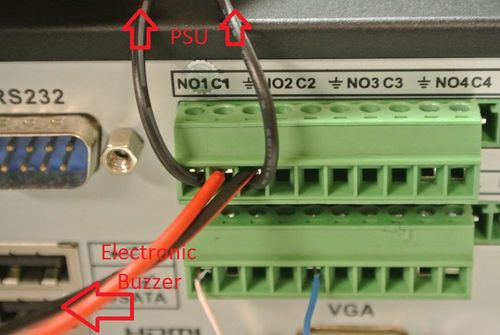
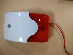
1. Here is your Electronic Buzzer, please read the product guide for this sensor to determine which lead is the power positive (ALARM OUT C1) and which lead is the Negative/Ground ⏚ in the event that the alarm is unidirectional and not bidirectional.
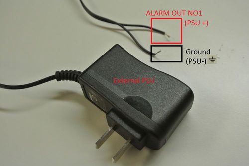
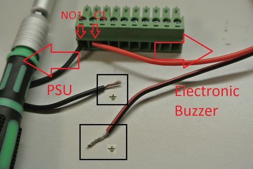
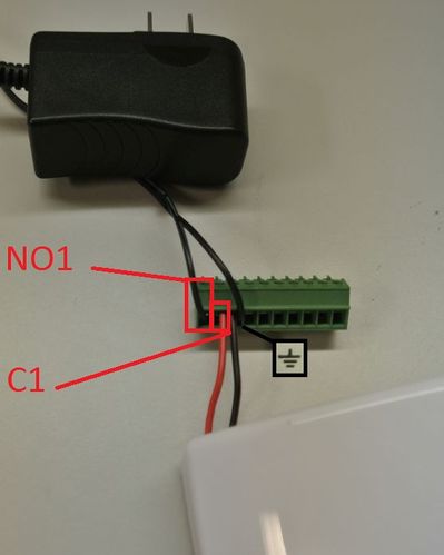
2. Also refer to the power requirements and specifications in order to make sure you are using the proper power supply unit for this device. Also Identify your power supply leads PSU+ and PSU- or Negative/Ground ⏚. PSU+ will go to ALARM OUT NO1.
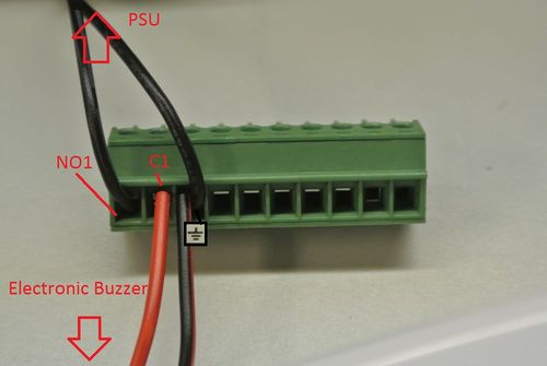
3. Take the Electronic Buzzer and seat the positive lead it into the power block corresponding to ALARM OUT C1
4. Take the PSU and seat the positive lead it into the power block corresponding to ALARM OUT NO1
5. Now seat both the PSU and Electronic Buzzer's Negative/Ground ⏚ leads into any of the corresponding alarm out Negative/Ground ⏚ terminals on the NVR/HCVR/DVR
6. Now double check and make sure you have everything setup according to all of your device's (NVR/HCVR/DVR PSU and Electronic Buzzer) specifications. Also check that the leads are seated properly in the power block and are making full metal to metal contact with the power block.
7. Now Connect the power block to the corresponding ALARM OUT area, and plug in your power supply.
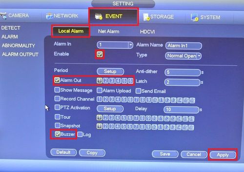
8. For testing purposes use this setup on your NVR/HCVR/DVR to make sure your setup works. Main Menu > Event (under settings) > click on Alarm tab > Enable Alarm > Select Alarm Out 1 > Enable Buzzer > click Apply.
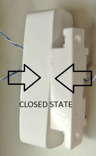
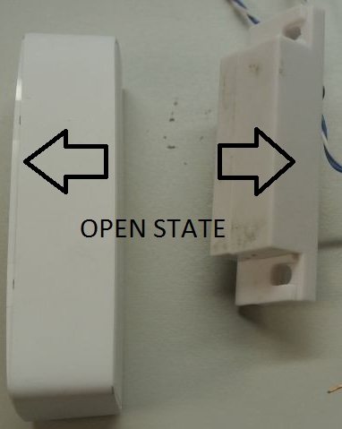
9. Now trigger you magnetic sensor and you should hear the NVR/HCVR/DVR's Buzzer, and also now your Electronic Buzzer should be alarming out.
Now you know how to setup both alarm inputs (magnetic sensor) and powered alarm outputs (Electronic Buzzer)!
Please check all of your systems (NVR/HCVR/DVR PSU and Electronic Buzzer) power requirements and specifications before plugging things in without any understanding of how it works, as this can result in possible electrical fires or even the death of your systems (NVR/HCVR/DVR PSU and Electronic Buzzer).Instructions
Prerequisites
Video Instructions
Step by Step Instructions
Brief Description: We will be setting up an Alarm Buzzer/Strobe light to the alarm output of our Recorder. It will be triggered by a Camera's Motion Detection Event.
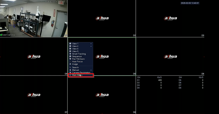
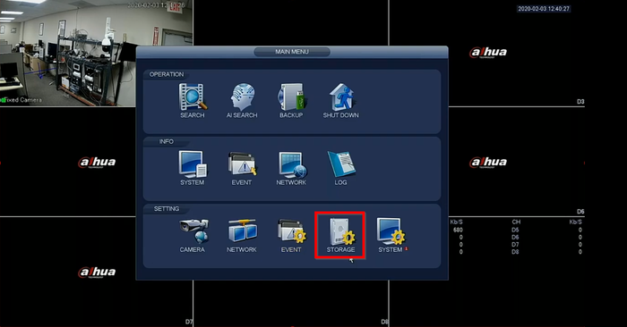
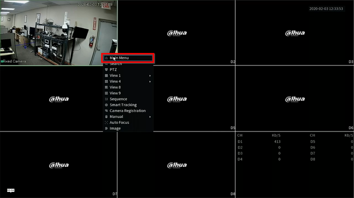
1.Go to Main Menu
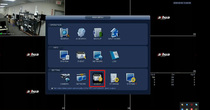
2. Click on Events
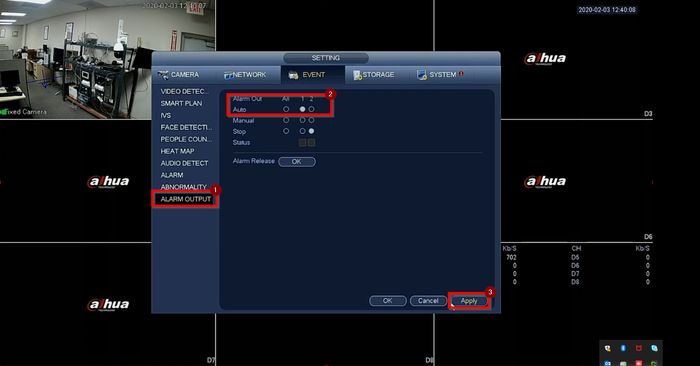
3. On "Alarm Output" we select the relay our Buzzer is connected to. In this case Relay 1. Click on Apply and then Ok to save.
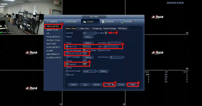
4. Next select "Video Detection" on the left and check the Enable box.
- Check Alarm Out and select the relay the buzzer is connected to
- Check Record Channel and the channel you want to record to when the event it tripped
- Check Snapshot if you'd like to store snapshots
Click on Apply and Ok to save
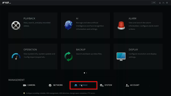
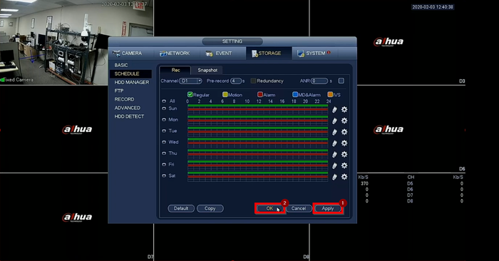
5. Got back to the main menu and select Storage
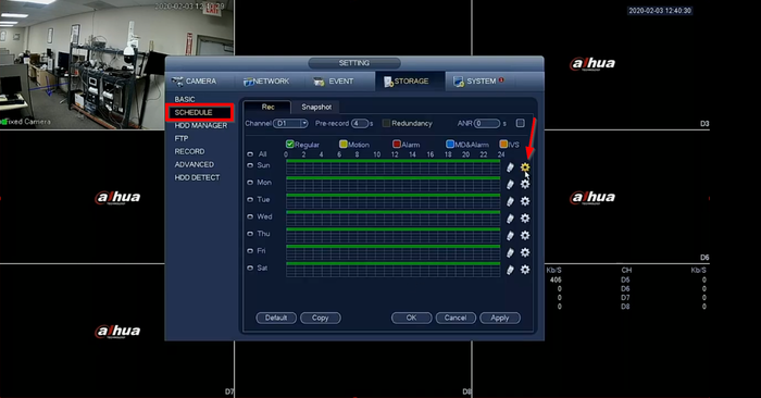
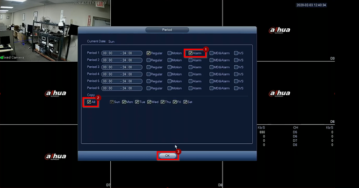
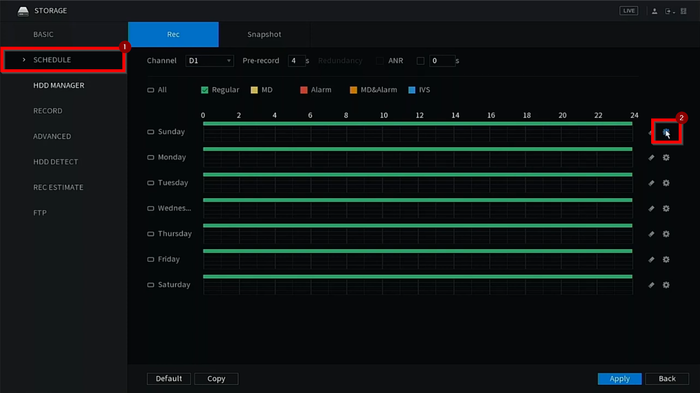
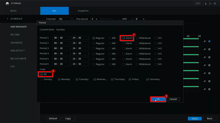
6. Select Schedule on the left menu and click on the "settings" icon. On the pop up menu check "Alarm" and "All" for all days of the week. Hit OK to go back
7. Click on Apply and Ok to save
Prerequisites
Video Instructions
Step by Step Instructions
1. Go to the Main Menu
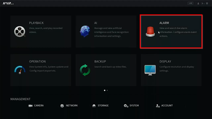
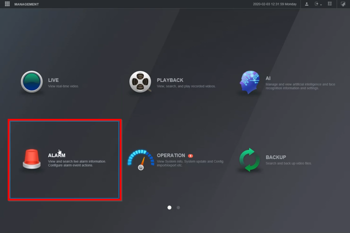
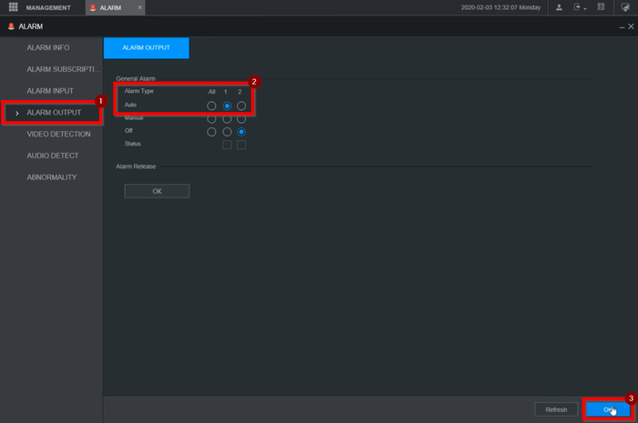
2. Go to Alarm
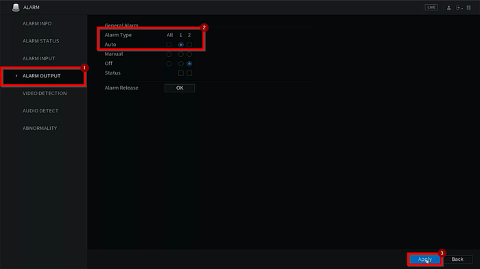
3. Select Alarm Output on the left menu and place the relay the buzzer is connected to on "auto". Click on apply to save
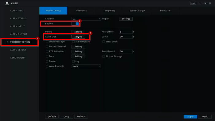
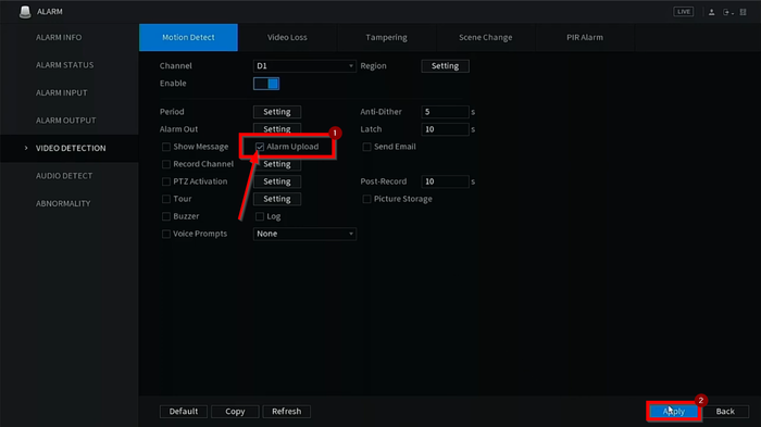
4. Select Video Detection on the left menu and Enable the event. Click on the setting tab next to Alarm out
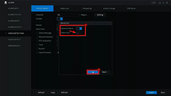
5. Make sure it is on and select the Relay the buzzer is wired to. Click OK
6. Check the Alarm Upload box and hit apply to save the configuration
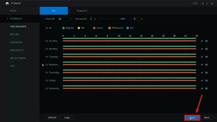
7. Go back to the Main menu and go to Storage
8. Select Schedule on the left menu and click on the "Settings" icon
9. Select Alarm and "All" for all days of the week. Select OK
10. Click on Apply to finalize the settings
Prerequisites
Video Instructions
Step by Step Instructions
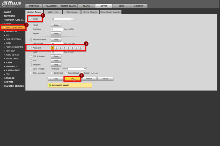
1. Login to the camera's WEBUI
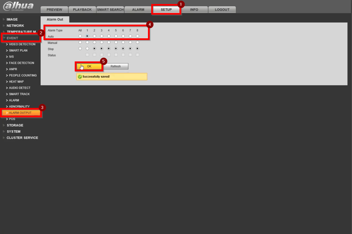
2. Go to Setup>Event>Alarm Output and select the relay the buzzer is wired too. Hit OK to save.
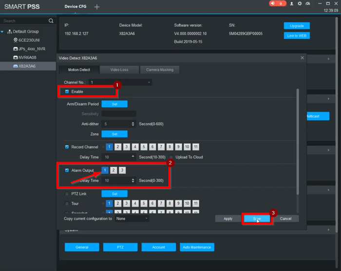
3. Go to Video Detection on the left menu. Enable Motion Detection, Alarm Out (With the corresponding relay), and hit okay to save
Prerequisites
Video Instructions
Step by Step Instructions
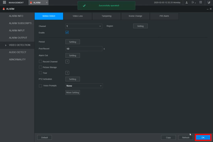
1. Login to the WEBUI
2. Go to Alarm
3. Select Alarm Output on the left menu and enable the relay the buzzer is wired to
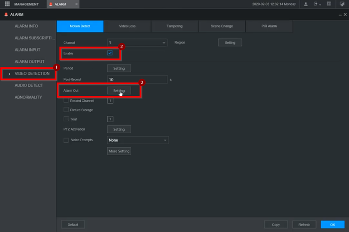
4. Select Video detection on the left menu. Enable Motion Detection and go to Alarm Out settings.
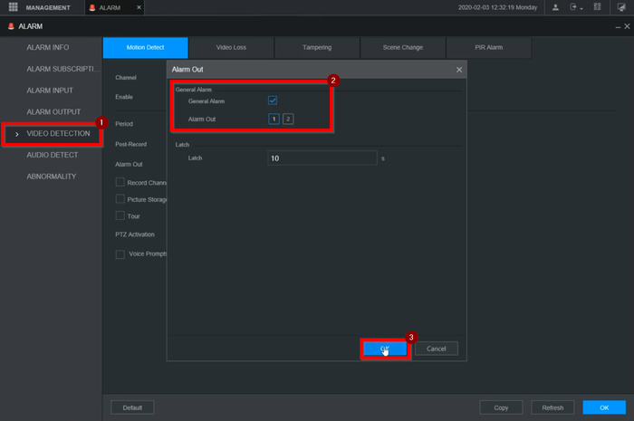
5. Check the General Alarm box and select the relay to enable. Click on OK
6. Click on OK to save and finalize the settings
Prerequisites
Video Instructions
Step by Step Instructions
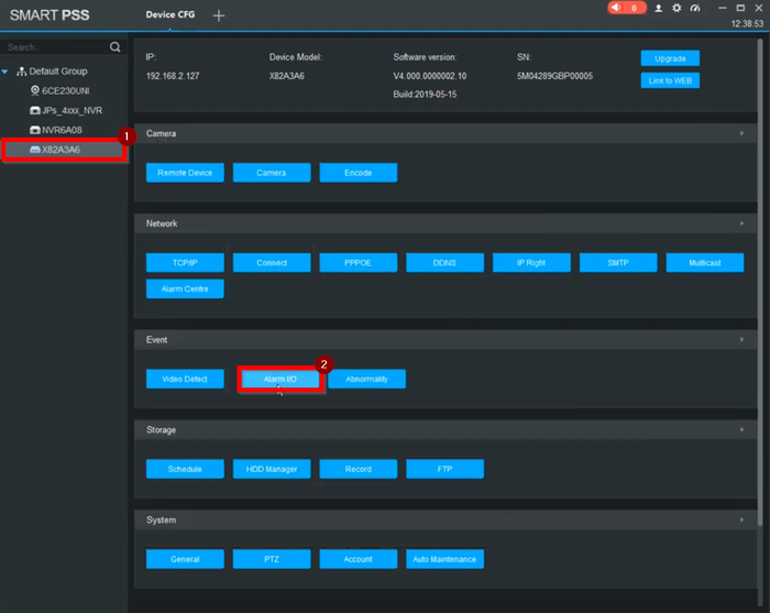
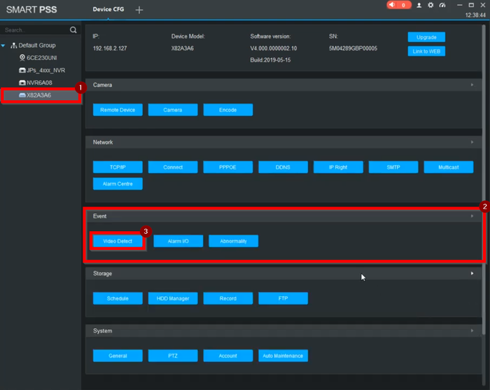
1. Select the Recorder on the left menu and go to "Alarm I/O" under Event
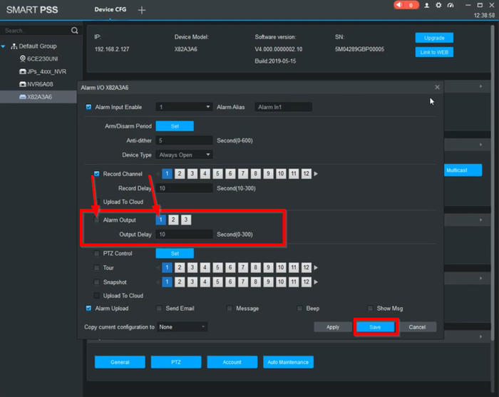
2. Make sure that Alarm Output is Enabled and select the relay the buzzer is wired to. Click on Save
3. Under Event, go to Video Detection
4. Make sure Motion Detection is enabled and Alarm out enabled as well. Select the relay the buzzer is wired to.
