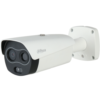
Difference between revisions of "USA/IPCamera/PTZ/Thermal/DH-TPC-BF5421-TD"
| (22 intermediate revisions by 5 users not shown) | |||
| Line 5: | Line 5: | ||
|- | |- | ||
!|Specifications | !|Specifications | ||
| − | |||
!|Manual | !|Manual | ||
| − | !|Firmware | + | !|Firmware |
| − | !| | + | !|Core Firmware |
|- | |- | ||
| − | |{{Template: | + | |{{Template:DH_TPC_BF5421_T_Specification_Template}} |
| − | | | + | |<!--{{Template:Thermal-Manual}}--> |
| − | + | ||
| − | |{{Template:DH_TPC-BF7X21-5421- | + | |{{Template:DH_TPC-BF7X21-5421-2221_Temperature_Monitoring}} |
|{{Template:PacketCamera_TPC-NYX5400-TDCXB}} | |{{Template:PacketCamera_TPC-NYX5400-TDCXB}} | ||
| + | |||
|- | |- | ||
|} | |} | ||
| − | |||
| − | |||
| − | + | [[file:TPC BF2221N B3 image.png|right|350px]] | |
| − | + | ||
| − | |||
| − | |||
| − | |||
| − | |||
| − | + | * [[Thermal/Firmware Update/TPC BF5421 T|How To Update TPC-BF5421-T Firmware]] | |
| − | * | ||
| − | |||
| − | |||
| − | |||
| − | |||
| − | |||
| − | |||
| − | |||
| − | === | + | ===Features=== |
| − | |||
| − | |||
| − | |||
| − | |||
| − | === | + | ===Wire Diagram=== |
| − | {| class="wikitable" | + | {| class="wikitable" style="display: inline-table;" |
| + | |+Alarm Wire Harness | ||
| + | |- | ||
| + | !colspan="2"|Cable Color | ||
| + | !|Cable Name | ||
| + | |- | ||
| + | |Blue | ||
| + | |[[File:Wire_blue.svg|35px]] | ||
| + | |ALARM_NO1 | ||
| + | |- | ||
| + | |Green | ||
| + | |[[File:Wire_green.svg|35px]] | ||
| + | |ALARM_COM1 | ||
| + | |- | ||
| + | |Grey | ||
| + | |[[File:Wire_Grey.png|35px]] | ||
| + | |ALARM_NO2 | ||
| + | |- | ||
| + | |Pink | ||
| + | |[[File:Wire_pink.png|35px]] | ||
| + | |ALARM_COM2 | ||
| + | |- | ||
| + | |Purple | ||
| + | |[[File:Wire_purple.png|35px]] | ||
| + | |ALARM_IN1 | ||
| + | |- | ||
| + | |Brown | ||
| + | |[[File:Wire_brown.svg|35px]] | ||
| + | |ALARM_IN2 | ||
| + | |- | ||
| + | |Green&Yellow | ||
| + | |[[File:Wire_Green_Yellow.png|35px]] | ||
| + | |GROUND | ||
| + | |- | ||
| + | |} | ||
| + | {| class="wikitable" style="display: inline-table;" | ||
| + | |+RS485 | ||
| + | |-RS485 | ||
| + | !colspan="2"|Cable Color | ||
| + | !|Cable Name | ||
| + | |- | ||
| + | |Yellow | ||
| + | |[[File:Wire_yellow.svg|35px]] | ||
| + | |RS485_A | ||
| + | |- | ||
| + | |Orange | ||
| + | |[[File:Wire_orange.svg|35px]] | ||
| + | |RS485_B | ||
| + | |- | ||
| + | |} | ||
| + | {| class="wikitable" style="display: inline-table;" | ||
| + | |+Other | ||
| + | !colspan="2"|Cable Color | ||
| + | !|Cable Name | ||
| + | |- | ||
| + | |White | ||
| + | |[[File:Cat5_Icon12.png|35px]] | ||
| + | |Ethernet Port | ||
| + | |- | ||
| + | |White | ||
| + | |[[file:Power_in_Icon12.png|35px]] | ||
| + | |Power Connection(Female) | ||
| + | |- | ||
| + | |White | ||
| + | |[[file:BNC_Icon12.png|35px]] | ||
| + | |BNC Connection(Male) | ||
| + | |- | ||
| + | |Yellow 3.5mm | ||
| + | |[[file:Audio_Out_Icon12.png|35px]] | ||
| + | |Audio Out 3.5mm (Female) | ||
|- | |- | ||
| − | + | |White | |
| − | + | |[[file:Audio_In_Icon12.png|35px]] | |
| − | + | |Audio In 3.5mm (Female) | |
|- | |- | ||
| − | |||
| − | |||
| − | |||
|} | |} | ||
| − | ==Product Images== | + | ===Product Images=== |
{| class="wikitable" | {| class="wikitable" | ||
|- | |- | ||
| Line 73: | Line 121: | ||
|} | |} | ||
| − | + | ||
| − | |||
[[Category:Model Specific Pages]] | [[Category:Model Specific Pages]] | ||
Latest revision as of 16:19, 20 June 2024
DH-TPC-BF5421-TD
| Specifications | Manual | Firmware | Core Firmware |
|---|---|---|---|
Build Date: 06-30-2021
|
Build Date: 07-03-2020
|
Features
Wire Diagram
| Cable Color | Cable Name | |
|---|---|---|
| Blue | 35px | ALARM_NO1 |
| Green | 35px | ALARM_COM1 |
| Grey | ALARM_NO2 | |
| Pink | ALARM_COM2 | |
| Purple | ALARM_IN1 | |
| Brown | File:Wire brown.svg | ALARM_IN2 |
| Green&Yellow | GROUND | |
| Cable Color | Cable Name | |
|---|---|---|
| Yellow | 35px | RS485_A |
| Orange | 35px | RS485_B |
| Cable Color | Cable Name | |
|---|---|---|
| White | Ethernet Port | |
| White | Power Connection(Female) | |
| White | BNC Connection(Male) | |
| Yellow 3.5mm | Audio Out 3.5mm (Female) | |
| White | Audio In 3.5mm (Female) | |
Product Images
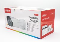
|
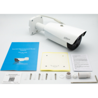
|
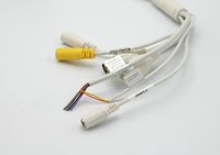
|
|
|
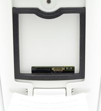
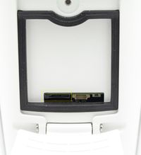
| Product Box | Box Contents | Wire Harness | Reset Button | SD-Card Slot |
|---|
