Difference between revisions of "PFM900 To IP Camera Video Test"
(→How to Test Video In with PFM900) |
(→PFM900 to IP Camera (and PoE) Video Test PFM900) |
||
| Line 10: | Line 10: | ||
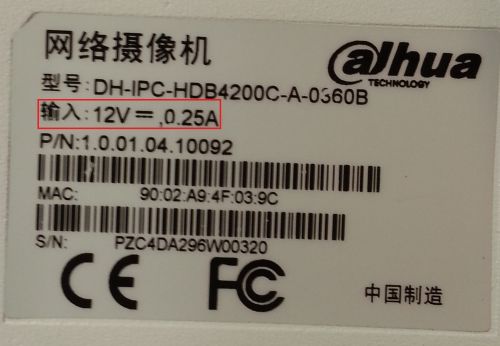
Make sure the Cameras power requirements do not exceed 12v/2a otherwise the PFM900 will not power the device due to power output limitations. If this happens you will need to power it via an additional dc wall outlet adapter on the cameras dc power harness adapter port. Also, don't forget that an IP camera might require up to 3 minutes to boot and register on any network even this device! | Make sure the Cameras power requirements do not exceed 12v/2a otherwise the PFM900 will not power the device due to power output limitations. If this happens you will need to power it via an additional dc wall outlet adapter on the cameras dc power harness adapter port. Also, don't forget that an IP camera might require up to 3 minutes to boot and register on any network even this device! | ||
| + | |||
[[file:20160225_105520.jpg|500x500px]] | [[file:20160225_105520.jpg|500x500px]] | ||
| + | |||
1. Power on your PFM900 Device, if it does not power on check [[PFM900_How_To_Charge_The_Battery|How to Charge the PFM900]] | 1. Power on your PFM900 Device, if it does not power on check [[PFM900_How_To_Charge_The_Battery|How to Charge the PFM900]] | ||
| + | |||
[[file:20160225_104216.jpg|500x500px]] | [[file:20160225_104216.jpg|500x500px]] | ||
| + | |||
2. Connect the camera or network switch (or PoE) or router to the blue PSE port via Ethernet cable for POE | 2. Connect the camera or network switch (or PoE) or router to the blue PSE port via Ethernet cable for POE | ||
| + | |||
[[file:20160225_104304.jpg|500x500px]] | [[file:20160225_104304.jpg|500x500px]] | ||
| + | |||
3. Now select "ONVIF Test" and press the right arrow button | 3. Now select "ONVIF Test" and press the right arrow button | ||
| + | |||
[[file:20160225_104311.jpg|500x500px]] | [[file:20160225_104311.jpg|500x500px]] | ||
| + | |||
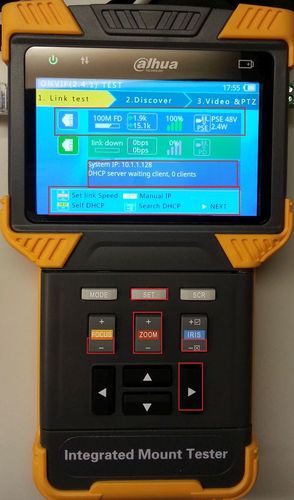
4. You will now see the Link test screen, the purpose of this screen is to show you the Link metrics that the PFM900 can read. | 4. You will now see the Link test screen, the purpose of this screen is to show you the Link metrics that the PFM900 can read. | ||
| Line 44: | Line 52: | ||
Once finished with setting the PFM900's IP address please press the right arrow button. | Once finished with setting the PFM900's IP address please press the right arrow button. | ||
| + | |||
[[file:20160225_104342.jpg|500x500px]] | [[file:20160225_104342.jpg|500x500px]] | ||
| Line 49: | Line 58: | ||
5. You should now be in the discover tab which finds ip's either on the network | 5. You should now be in the discover tab which finds ip's either on the network | ||
| + | |||
[[Category:Troubleshoot]][[Category:PFM900]][[Category:Accessories]][[Category:Model Specific Pages]][[Category:Video]] | [[Category:Troubleshoot]][[Category:PFM900]][[Category:Accessories]][[Category:Model Specific Pages]][[Category:Video]] | ||
Revision as of 20:57, 26 February 2016
PFM900 to IP Camera (and PoE) Video Test PFM900
PFM900 to IP Camera (PoE) Video Test Instructions
Pre-Requisites
- PFM900
- IP Camera, HDCVI Camera, or Analog Camera
- Power adapter for IP, HDCVI, or Analog cameras over 2amps input
- Ethernet or HDCVI cable
Make sure the Cameras power requirements do not exceed 12v/2a otherwise the PFM900 will not power the device due to power output limitations. If this happens you will need to power it via an additional dc wall outlet adapter on the cameras dc power harness adapter port. Also, don't forget that an IP camera might require up to 3 minutes to boot and register on any network even this device!
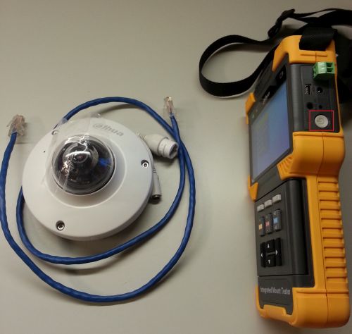
1. Power on your PFM900 Device, if it does not power on check How to Charge the PFM900
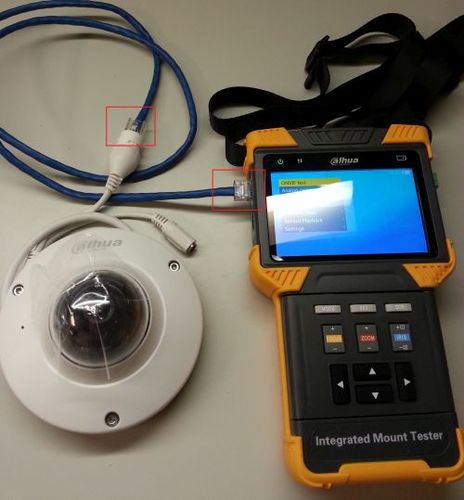
2. Connect the camera or network switch (or PoE) or router to the blue PSE port via Ethernet cable for POE
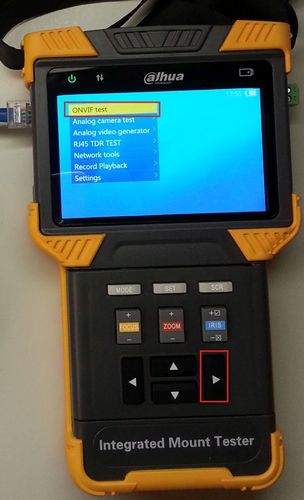
3. Now select "ONVIF Test" and press the right arrow button
4. You will now see the Link test screen, the purpose of this screen is to show you the Link metrics that the PFM900 can read.
This screen indicates (from right to left):
- The speed you are connected at (10/100/1000 mbps)
- The amount of data in and out of the IP Camera
- The health of the connection (represents signal over distance of cable)
- The (Blue) PSE which is the PoE output port or (below is Green) PD which is the PoE input (both are for data)
- At the end is a Voltage and Wattage indicator.
Below this area is:
- The system ip, which acts as a host to the device(s) connected
Below this is the button map:
- Pressing the "ZOOM +" and "ZOOM -" button will "Set link Speed" up or down (10/100/1000 mbps)
- Pressing the "SET" button will manually let you configure your host ip for the PFM900
- Pressing the "Focus -" button will Self DHCP automatically fetching an IP (Hosting IP, requesting device domain [i.e. ip camera] with PFM900)
- Pressing the "IRIS -" button will Search DHCP to automatically fetch an IP (Connecting to a hosting IP with PFM900)
- Pressing the "->" (right arrow) button will send you to the Discover tab
Once finished with setting the PFM900's IP address please press the right arrow button.
5. You should now be in the discover tab which finds ip's either on the network
