Difference between revisions of "Access Control/Products/ASR1101A"
(Created page with "=DHI-ASR1101A= __NOTOC__ {| class="wikitable" style="width: 100%;" |+DHI-ASR1101A |- !|Specifications !|Quick Start Guide !|Manual !|Firmware |- |{{Template:DHI-ASR1101A_Speci...") |
|||
| Line 5: | Line 5: | ||
|- | |- | ||
!|Specifications | !|Specifications | ||
| − | |||
!|Manual | !|Manual | ||
!|Firmware | !|Firmware | ||
|- | |- | ||
|{{Template:DHI-ASR1101A_Specification_Template}} | |{{Template:DHI-ASR1101A_Specification_Template}} | ||
| − | |||
|<!--{{Template:IPCamera-Manual}}--> | |<!--{{Template:IPCamera-Manual}}--> | ||
|{{Template:General_ASR1101A}} | |{{Template:General_ASR1101A}} | ||
Latest revision as of 23:00, 10 August 2023
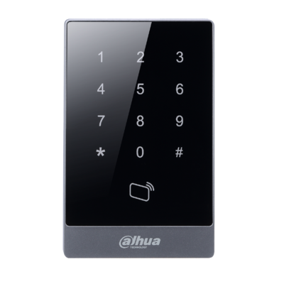
DHI-ASR1101A
| Specifications | Manual | Firmware |
|---|---|---|
Build Date: 12-24-2020
|
Features
- Wiegand26/34 bits RS-485 protocol
- 13.56MHz(Mifare)
- Red and Green LEDs
- Sensitive touch keypad with blue backlight
- Watch dog function ensure device free from halting
- Beep Buzzer and LED indicator
- Surface mounted installation
Wire Diagram
| Cable Color | Cable Name | Description | |
|---|---|---|---|
| Black | 35px | RD– | Negative electrode of external card reader. |
| Red | 35px | RD+ | Positive electrode of external card reader. |
| Blue | 35px | CASE | Tamper alarm input of the external card reader. |
| White | 35px | D1 | Wiegand D1 input |
| Green | File:Wire green.svg | D0 | Wiegand D0 input |
| Brown | File:Wire brown.svg | LED | Connected to external reader indicator in |
| Yellow | File:Wire yellow.svg | B | RS-485 negative electrode input |
| Purple | A | RS-485 positive electrode input | |
How to Update an Access Reader
- Download Firmware file
- Connect Reader to Door 1 connection on Door Controller (for example ASC1204B)
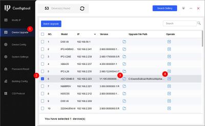
- Open ConfigTool
- Go to Device Upgrade - Locate firmware file and click Upgrade
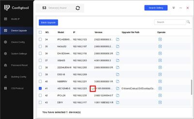
- A green check mark will confirm a successful upgrade


