Difference between revisions of "Access Control/Products/ASI1212D"
| Line 47: | Line 47: | ||
The wire labeled CON3 is used | The wire labeled CON3 is used | ||
| − | 2. Wire the connections in line with the desired devices (and power if required) to complete a | + | 2. Wire the connections in line with the desired devices (and power if required) to complete a circuit. |
In this example a light (and external power) is being used to show when the relay has been successfully triggered. | In this example a light (and external power) is being used to show when the relay has been successfully triggered. | ||
Revision as of 22:29, 26 November 2019
Contents
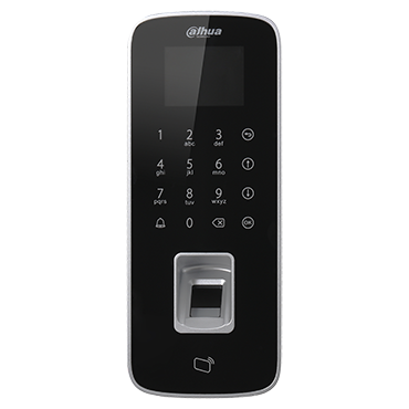
ASI1212D
Notice
Default IP address for this device is 192.168.1.108
User name: admin
Password: 888888888
or
User name: admin
Password: admin
Firmware Download
Features
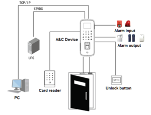
- Wiegand or RS-485 Interface to Reder
- TCP/IP to PC, Support for WAN Communication
- Touch Keyboard and LCD display
- Supports 30,000 Valid Cards and 150,000 Events
- Supports Card, Password, Fingerprint and a Combination of Credentials
- Add Devices in SmartPSS via P2P Connection
- Door Time Out, Intrusion, Duress and Tamper Alarms
- Anti-passback and Multi-card Open Options
- Supports 128 Efficient Time and Holiday Schedules
Wiring Guide
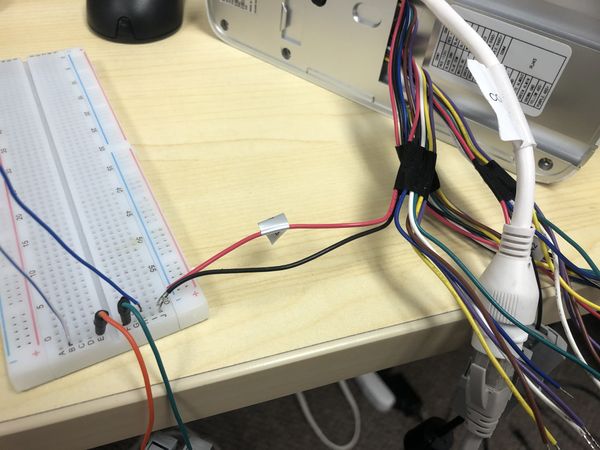
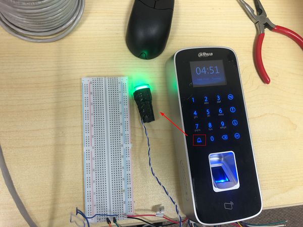
This guide demonstrates wiring the 'Ring' function. A light is in place to show when the relay has been successfully triggered
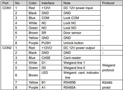
Please reference the device Wiring Guide for the correct relay connections for your purposes
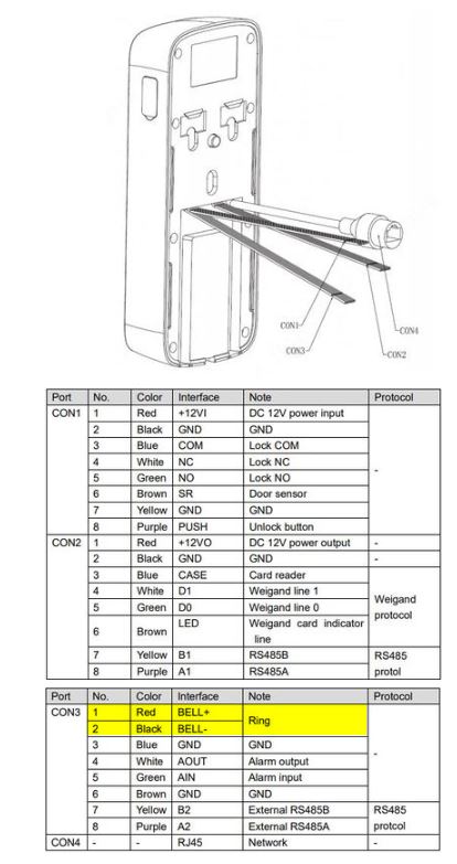
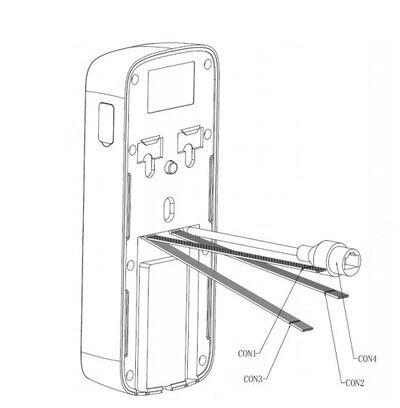
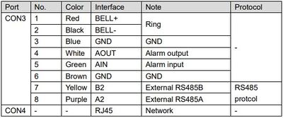
1. Check the wiring diagram to confirm what connections need to be made
For Ring function:
The wire labeled CON3 is used
2. Wire the connections in line with the desired devices (and power if required) to complete a circuit.
In this example a light (and external power) is being used to show when the relay has been successfully triggered.
3. After wiring the circuit press the Ring button and the relay should engage
In this example, the light will turn on
Specifications
| System | |
| Main Processor | 32-bit |
| Flash Memory | 32 MB |
| Input/Output Ports | |
| Inputs | One (1) Door Sensor |
| One (1) Exit Button | |
| One (1) Alarm | |
| Outputs | Three (3) Alarm Relays (Door Lock, Bell, Alarm) |
| Card Reader | |
| Format | 13.56 MHz MIFARE |
| Range | 3 cm to 8 cm (1.18 in. to 3.15 in.), maximum |
| Response Time | < 0.1 s |
| Fingerprint Reader | |
| Response Time | ≤ 0.5 s |
| Recognition Time | ≤ 1.5 s |
| FAR | ≤ 0.00004% |
| FRR | ≤ 0.15% |
| Capacity | |
| Card Holders | 30,000 |
| Events | 150,000 |
| Fingerprints | 3000 |
| Functions | |
| Network | P2P, DHCP |
| Access Control | Anti Pass-back, Multi-interlock, Multi-card Unlock |
| User Management | General, VIP, Guest, Patrol, Black List, Duress |
| Alarm Functions | Door time-out, Intrusion, Duress,Tamper |
| Schedule Settings | Schedule: 128 Groups |
| Period: 128 Groups | |
| Holiday: 128 Groups | |
| RTC | Supported |
| Voice Prompt | Supported |
| Audible Indicator | Buzzer |
| Interface | |
| To PC | RJ45 (10/100 Mbps) |
| To Reader | Wiegand 34/26, RS485 |
| Certifications | |
| Safety | EN 60950:2006+A2:2013 |
| Conforms to UL Standards | |
| Electromagnetic Compatibility (EMC) | FCC CFR 47 Part 15 subpart B |
| EN 55022:2010/AC:2011 (Class B) | |
| EN 55024:2010, EN 50130-4:2011, | |
| EN 61000-6-3:2007/A1:2011 | |
| EN 61000-3-2:2006+A1:2009+A2:2009 | |
| EN 61000-3-3:2013, | |
| IEC 61000-4-2:2008, IEC 61000-4-3:2006+A1:2007 | |
| IEC 61000-4-4:2012, IEC 61000-4-5:2005, | |
| IEC 61000-4-6:2008, IEC 61000-4-8:2009 | |
| IEC 61000-4-11:2004 | |
| Electrical/Environmental | |
| Power Supply | 9 to 15 VDC, 200 mA |
| Operating Temperature | -5° C to +55° C (23° F to +131° F), 95% RH |
| Ingress Protection | IP65 |
| Construction | |
| Dimensions | 205.0 mm x 83.0 mm x 33.0 mm |
| (8.07 in. x 3.26 in. x 1.30 in.) | |
| Net Weight | 0.44 kg (0.97 lb) |
| Accessory - IC Card | |
| Model Number | MF11CS50 |
| Standard | MIFARE S50, 13.56 MHz |
| Compatibility | ISO/IEC 14443A |
| Range | Approximately 10 cm (3.94 in.) |
| Dimensions | 86.0 mm x 54.0 mm x 0.80 mm |
| (3.39 in. x 2.13 in. x 0.03 in.) | |
| Weight | 0.006 kg (0.013 lb) |
| Manufacturer/Brand | Dahua |
