Access Control/Products/ASI1212D
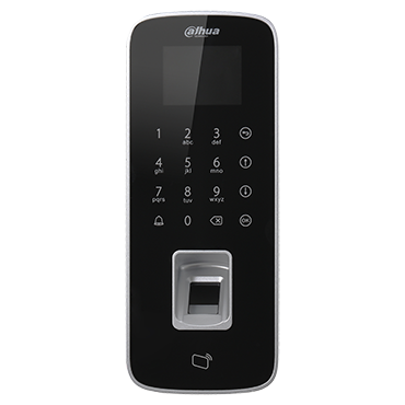
ASI1212D
| Specifications | Quick Start Guide | Manual | Firmware |
|---|---|---|---|
| Coming Soon |
Build Date: 08-11-2021
|
Notice
Default IP address for this device is 192.168.1.108
User name: admin
Password: 888888888
or
User name: admin
Password: admin
Features
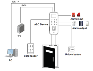
- Wiegand or RS-485 Interface to Reder
- TCP/IP to PC, Support for WAN Communication
- Touch Keyboard and LCD display
- Supports 30,000 Valid Cards and 150,000 Events
- Supports Card, Password, Fingerprint and a Combination of Credentials
- Add Devices in SmartPSS via P2P Connection
- Door Time Out, Intrusion, Duress and Tamper Alarms
- Anti-passback and Multi-card Open Options
- Supports 128 Efficient Time and Holiday Schedules
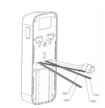
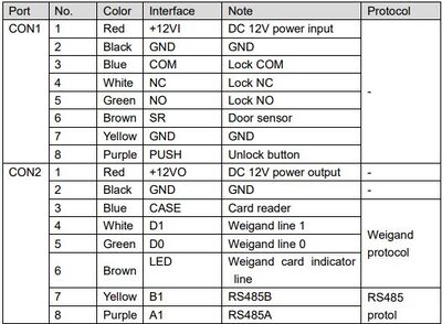
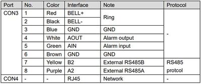
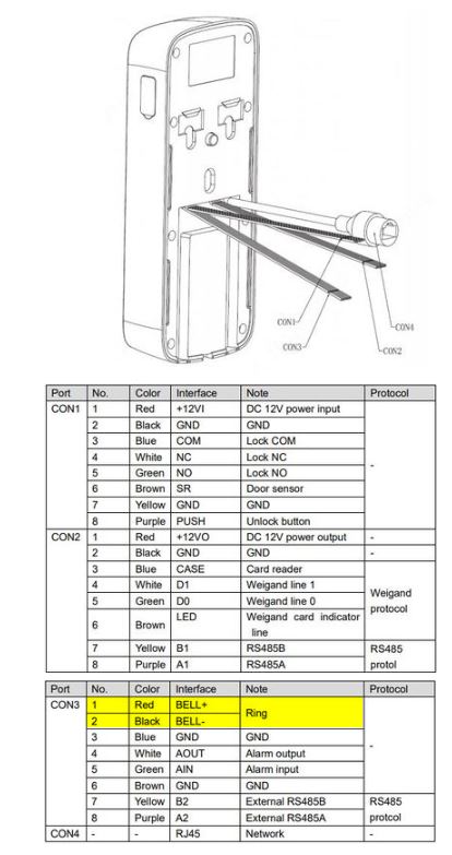
ASI1212D Wiring Chart
Wiring Guide
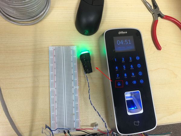
This guide demonstrates wiring the 'Ring' function. A light is in place to show when the relay has been successfully triggered
Please reference the device Wiring Guide for the correct relay connections for your purposes
1. Check the wiring diagram to confirm what connections need to be made
For Ring function:
The Red and Black wires labeled CON3 are used
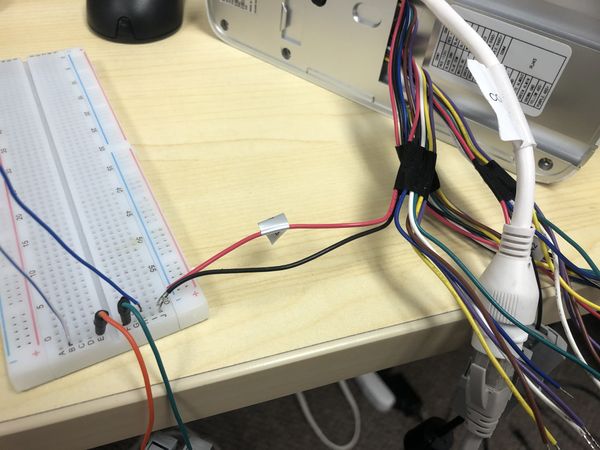
2. Wire the connections in line with the desired devices (and power if required) to complete a circuit.
In this example a light (and external power) is being used to show when the relay has been successfully triggered.
3. After wiring the circuit press the Ring button and the relay should engage
In this example, the light will turn on
Specifications
